Jet controlled ignition plug for rotor engine

A rotary engine and jet control technology, applied in combustion engines, machines/engines, internal combustion piston engines, etc., can solve the problems of easy dissipation of ignition energy, and achieve the effect of overcoming easy dissipation.

Active Publication Date: 2019-08-20
JIANGSU UNIV
View PDF6 Cites 0 Cited by
  • Summary
  • Abstract
  • Description
  • Claims
  • Application Information

AI Technical Summary

Problems solved by technology

Since the spark plug is installed in the ignition chamber, the flow field environment where the spark plug of the rotary engine is located changes from a high-speed unidirectional flow to a low-speed eddy current, which overcomes the problem that the ignition energy is easily lost

Method used


Image

  • Jet controlled ignition plug for rotor engine
  • Jet controlled ignition plug for rotor engine
  • Jet controlled ignition plug for rotor engine

Examples


Embodiment Construction

[0028] The present invention will be further described below in conjunction with the accompanying drawings and specific embodiments, but the protection scope of the present invention is not limited thereto.

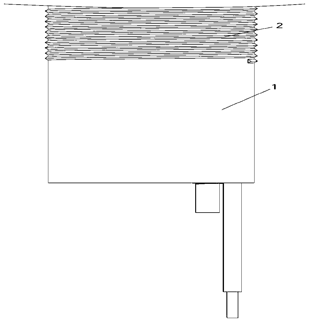
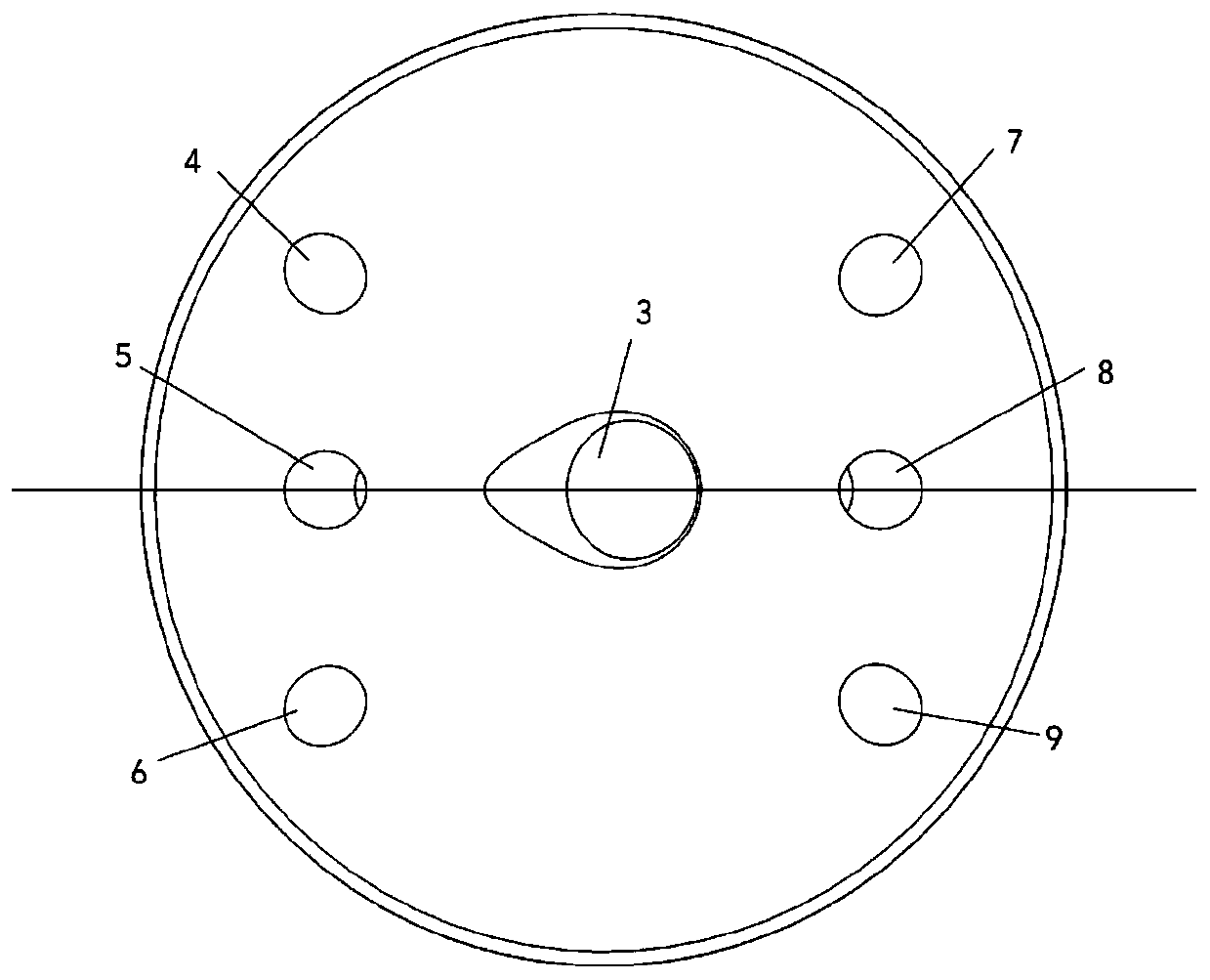
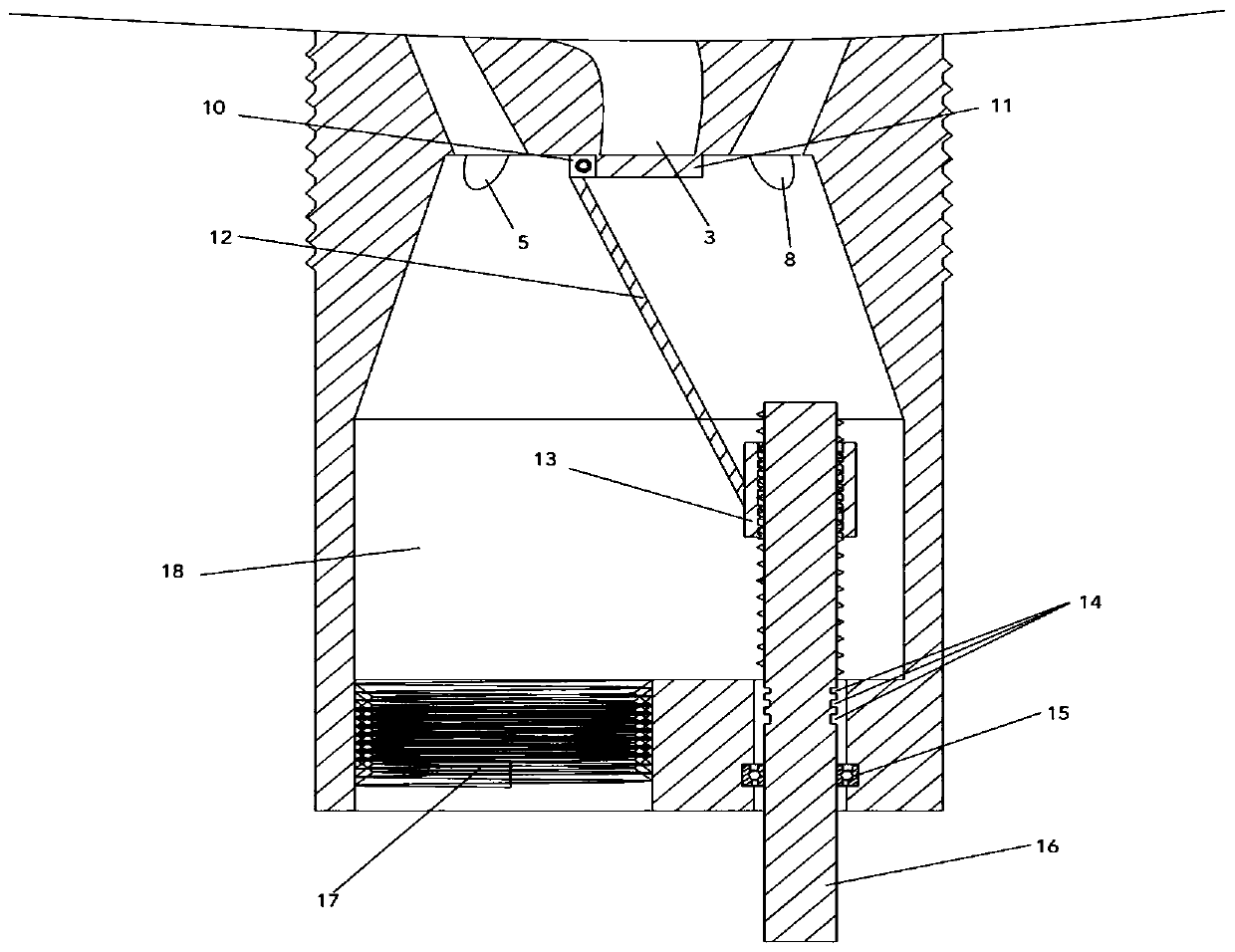
[0029] Such as figure 1 and figure 2 As shown, the jet control ignition plug of the rotary engine according to the present invention, the jet control ignition plug 1 is installed on the engine cylinder through the external thread 2, and the jet control ignition plug 1 includes an ignition chamber 18, a main intake pipe 3 and The jet tube, the premixing chamber communicates with the combustion chamber in the engine through the main intake pipe 3 and the jet tube, the main intake pipe 3 is provided with a valve 11, and the valve 11 is opened and closed by the slider crank mechanism; the ignition The plug 18 is provided with a spark plug installation hole 17, and the spark plug is installed in the spark plug installation hole 17. The main air intake pipe 3 is a curved pip...


PUM


Abstract

The invention provides a jet controlled ignition plug for a rotor engine. The jet controlled ignition plug is mounted on an engine cylinder and comprises an ignition chamber, a main gas inlet pipe andjet pipes; the ignition chamber communicates with an engine combustion chamber through the main gas inlet pipe and the jet pipes; a valve is arranged on the main gas inlet pipe; the valve is opened or closed through a sliding block-crank mechanism; and a spark plug is mounted in the ignition chamber. The main gas inlet pipe is a bent pipe and is positioned in the centre of a premixing chamber; and a plurality of the jet pipes are symmetrically distributed around the main gas inlet pipe. One end of a connecting rod is hinged to the valve; the other end of the connecting rod is hinged to a sliding block; and a sliding blocks performs linear movement through an executing mechanism so that the valve is opened or closed. According to the jet controlled ignition plug for the rotor engine, the mixed gas in a cylinder enters the ignition chamber conveniently, so that the flow field environment where the spark plug of the rotor engine is positioned is changed from high-speed single-direction flow into low-speed eddy current; and therefore, the problem that ignition energy is easily dissipated is solved.

Description

technical field [0001] The invention relates to the technical field of power machinery systems, in particular to a jet control spark plug of a rotary engine. Background technique [0002] As a novel internal combustion engine, the rotary engine has the advantages of simple structure, few parts and high power-to-weight ratio, so the rotary engine is widely used in many fields. However, although the rotary engine has a series of superior performances, it also has the serious defect of poor fuel economy. Therefore, it is imperative to improve the combustion efficiency of the rotary engine. The key to improving the combustion efficiency of a rotary engine is to make the fuel burn more quickly and fully in the cylinder. As we all know, the combustion process in the cylinder of a rotary engine is largely restricted by the flow field in the cylinder. Regarding the flow field in the cylinder of the rotary engine, the unidirectional rotation of the rotor of the rotary engine cause...

Claims


Application Information

Patent Timeline
IPC IPC(8): F02B53/12F02B53/06F02B55/00
CPCF02B53/06F02B53/12F02B55/00Y02T10/12
Inventor 范宝伟康梓彬张耀元王远光潘剑锋
Owner JIANGSU UNIV
Why Eureka
Try Eureka