Conical wheel type stepless speed change mechanism

A technology of continuously variable transmission mechanism and cone wheel, which is applied in the direction of electromechanical devices, mechanical equipment, and control of mechanical energy, and can solve problems such as high production costs, high material requirements, and unstable performance.

Pending Publication Date: 2019-08-20
FUJIAN UNIV OF TECH
View PDF0 Cites 3 Cited by
  • Summary
  • Abstract
  • Description
  • Claims
  • Application Information

AI Technical Summary

Problems solved by technology

Existing CVTs include metal belt CVTs, chain CVTs or KRG cone-ring CVTs and other types; among them, metal belt CVTs or chain CVTs, the passive pulleys need a hydraulic system to accurately Control, complex structure, high production cost, easy damage or deformation of the transmissio

Method used


Image

  • Conical wheel type stepless speed change mechanism
  • Conical wheel type stepless speed change mechanism
  • Conical wheel type stepless speed change mechanism

Examples


Embodiment Construction

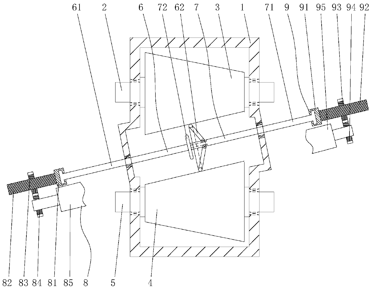
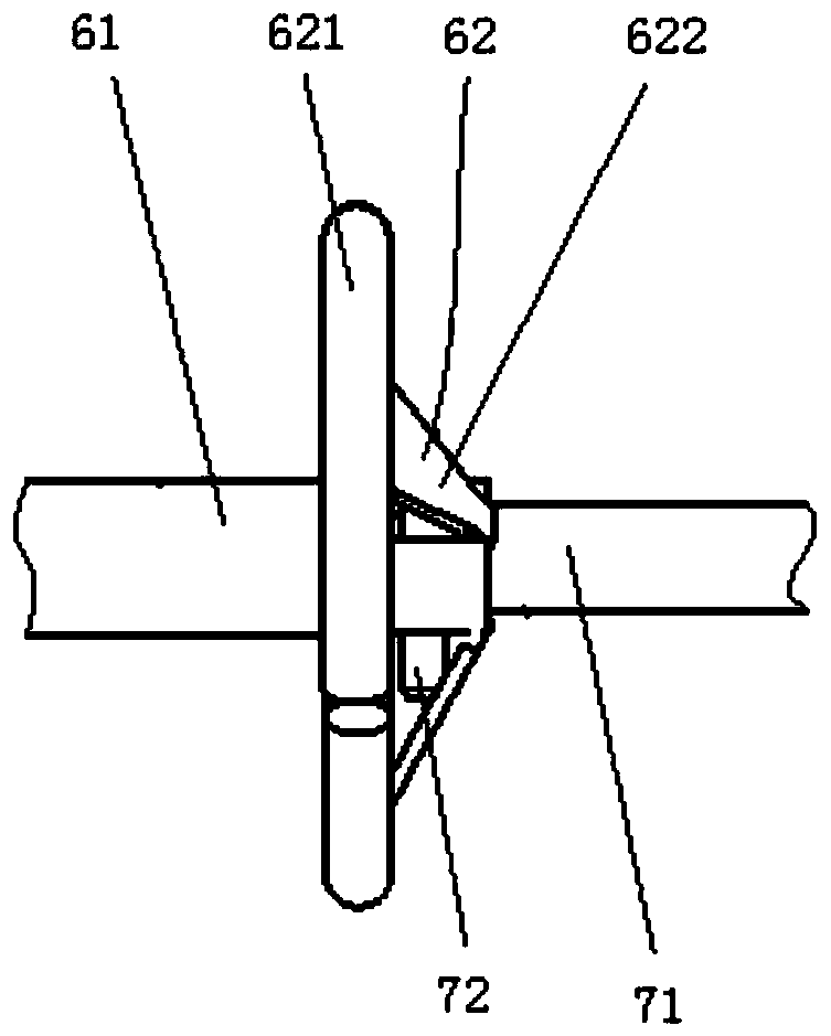
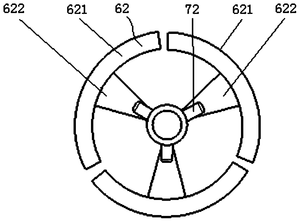
[0021] Such as Figure 1-6 As shown in one of them, the cone wheel type continuously variable transmission mechanism of the present invention includes a casing 1, a power input shaft 2 and a power output shaft 5, and the power input shaft 2 and the power output shaft 5 are installed in parallel in the casing 1, and the power The input shaft 2 and the power output shaft 5 are respectively fixed with an input cone wheel 3 and an output cone wheel 4 in opposite directions, and an umbrella-shaped expansion mechanism is arranged between the input cone wheel 3 and the output cone wheel 4, so that The umbrella expansion mechanism includes an umbrella mechanism 6, an expansion drive mechanism 7, and a position adjustment drive mechanism 8. The umbrella mechanism 6 includes an umbrella shaft 61 and a plurality of expansion parts 62. The umbrella shaft 61 is movably mounted on the chassis 1. On one side wall, the plurality of expansion parts 62 are rotatably connected to one end of the ...


PUM


Abstract

The invention relates to a conical wheel type stepless speed change mechanism. The conical wheel type stepless speed change mechanism comprises a case, a power input shaft and a power output shaft. The power input shaft and the power output shaft are arranged in the case in parallel, an input conical wheel and an output conical wheel with the opposite directions are fixed to the power input shaftand the power output shaft correspondingly, an umbrella-shaped expansion mechanism is arranged between the input conical wheel and the output conical wheel, and comprises an umbrella-shaped mechanism,an expansion driving mechanism and a positioning driving mechanism, the umbrella-shaped mechanism comprises an umbrella shaft and multiple expansion parts, an umbrella shaft is movably arranged on one side wall of the case in a penetrating manner, the expansion parts are rotatably connected to the periphery of one end of the umbrella shaft, and an umbrella shape is formed; the expansion parts aredriven by the expansion driving mechanism and are expanded outwards to be used for pressing the conical faces of the input conical wheel and the output conical wheel to communicate with power transmission, the other end of the umbrella shaft is rotatably connected with the positioning driving mechanism arranged outside the case, the positioning driving mechanism drives the umbrella shaft to drivethe multiple expansion parts to move in the axial direction of the umbrella shaft to be used for adjusting the pressing position to achieve the stepless speed change.

Description

technical field [0001] The invention relates to the technical field of transmissions, in particular to a bevel wheel type continuously variable transmission mechanism. Background technique [0002] Continuously variable transmission is a kind of transmission, which uses the transmission belt to cooperate with the driving and driven wheels with variable working diameter to transmit power, so as to realize the continuous change of transmission ratio. Existing CVTs include metal belt CVTs, chain CVTs or KRG cone-ring CVTs and other types; among them, metal belt CVTs or chain CVTs, the passive pulleys need a hydraulic system to accurately Control, complex structure, high production cost, easy damage or deformation of the transmission belt, resulting in unstable performance, and high requirements for materials; and the KRG cone-ring continuously variable transmission, which transmits power through the cone wheel and the transmission ring, not only has a complex structure, Moreov...

Claims


Application Information

Patent Timeline
IPC IPC(8): F16H3/06F16H57/023H02K7/116
CPCF16H3/06F16H57/023H02K7/116
Inventor 钟勇刘锐毋豪杰魏忠彬林宁
Owner FUJIAN UNIV OF TECH
Why Eureka
Try Eureka