Two-dimensional compensation method of optical fiber gyroscope magnetic temperature cross-linking coupling error

A fiber optic gyroscope and coupling error technology, applied in the field of fiber optic inertia, can solve the problems of gyroscope measurement accuracy drop, output error, etc.

Active Publication Date: 2019-08-20
ZHEJIANG UNIV
View PDF14 Cites 4 Cited by
  • Summary
  • Abstract
  • Description
  • Claims
  • Application Information

AI Technical Summary

Problems solved by technology

The output error generated by the joint action of the temperature field and the magnetic field gradually accum

Method used


Image

  • Two-dimensional compensation method of optical fiber gyroscope magnetic temperature cross-linking coupling error
  • Two-dimensional compensation method of optical fiber gyroscope magnetic temperature cross-linking coupling error
  • Two-dimensional compensation method of optical fiber gyroscope magnetic temperature cross-linking coupling error

Examples


Embodiment Construction

[0035] The present invention detects the magnetic field and temperature field information of the environment where the fiber ring is located in real time through a temperature sensor and a magnetic field sensor attached to the fiber ring, establishes a magnetic-temperature cross-linking coupling error model, and performs magnetic-temperature cross-linking on the fiber optic gyroscope according to the model Two-dimensional compensation of coupling errors.

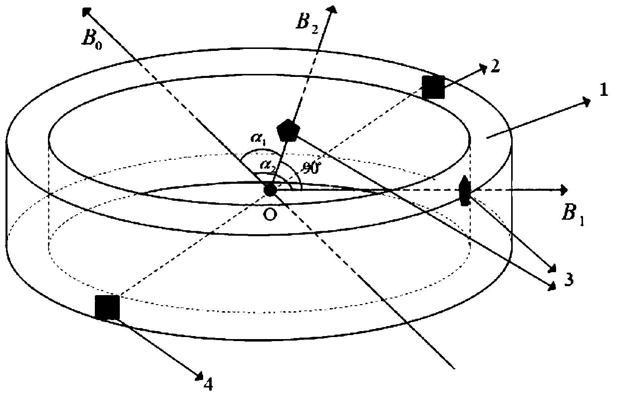
[0036] The fiber optic gyroscope magnetic-temperature cross-linking coupling error two-dimensional compensation technology of the present invention will be described in detail below in conjunction with the accompanying drawings, as figure 1 As shown, it is divided into the following steps.

[0037] A. A temperature sensor 2 is attached to the upper surface of the fiber optic ring 1 of the fiber optic gyroscope, and a temperature sensor 4 is attached to the lower surface;

[0038] B. Attach two magnetic field sensors 3 on th...


PUM


Abstract

The invention discloses a two-dimensional compensation method of an optical fiber gyroscope magnetic temperature cross-linking coupling error. The method comprises the following steps of A, attachingat least one temperature sensor to each of upper and lower surfaces of an optical fiber ring of an optical fiber gyroscope; B, attaching two magnetic field sensors to a side surface of the optical fiber ring of the optical fiber gyroscope, wherein magnetic sensitive shafts of the two magnetic field sensors are orthogonal to the side surface of the optical fiber ring and pass through a central axisof the optical fiber ring; C, through an experiment, acquiring an error model of a relationship among the optical fiber gyroscope magnetic temperature cross-linking coupling error, magnetic field distribution and temperature distribution, wherein the error model Y=B T (the Y is the optical fiber gyroscope magnetic temperature cross-linking coupling error, the B is the magnetic field distribution,and the T is the temperature distribution); and D, using the error model to compensate the optical fiber gyroscope magnetic temperature cross-linking coupling error in a two-dimensional mode. In theinvention, the optical fiber gyroscope magnetic temperature cross-linking coupling error is compensated through detecting a radial magnetic field and a temperature of an environment where the opticalfiber gyroscope is located in real time, a non-reciprocal error generated by the optical fiber gyroscope under a combined action of a magnetic field and a temperature field is effectively reduced, andenvironmental adaptability and application precision of the optical fiber gyroscope are finally increased.

Description

technical field [0001] The invention relates to the technical field of optical fiber inertia, in particular to a two-dimensional compensation method for the magnetic-temperature cross-linking coupling error of an optical fiber gyroscope. Background technique [0002] The interferometric fiber optic gyroscope measures the angular velocity of the carrier relative to the inertial space based on the Sagnac effect. A series of inherent advantages of the fiber optic gyroscope make it widely used in current inertial navigation systems. Complex physical fields such as magnetic field, temperature, and vibration in practical applications seriously reduce the accuracy of fiber optic gyroscopes and limit their application fields. [0003] The improvement of the navigation accuracy of the inertial measurement system requires a higher-precision fiber optic gyroscope, which is required to be adaptable to complex environments. Experiments have shown that when a high-precision fiber optic g...

Claims


Application Information

Patent Timeline
IPC IPC(8): G01C25/00
CPCG01C25/005
Inventor 张登伟梁璀
Owner ZHEJIANG UNIV
Why Eureka
Try Eureka