Calibration plate, calibration plate identification method and calibration plate identification device

A technology for calibration boards and recognition results, applied in image data processing, instruments, calculations, etc., can solve problems such as limited applicable scenarios, and achieve the effects of reducing interference, improving recognition accuracy, and improving accuracy

Inactive Publication Date: 2019-08-20
北京阿丘机器人科技有限公司
View PDF16 Cites 12 Cited by
  • Summary
  • Abstract
  • Description
  • Claims
  • Application Information

AI Technical Summary

Problems solved by technology

At present, due to the limited applicable scenarios, the existing calibration board cannot meet t

Method used


Image

  • Calibration plate, calibration plate identification method and calibration plate identification device
  • Calibration plate, calibration plate identification method and calibration plate identification device
  • Calibration plate, calibration plate identification method and calibration plate identification device

Examples


Example Embodiment

[0029] Example 1

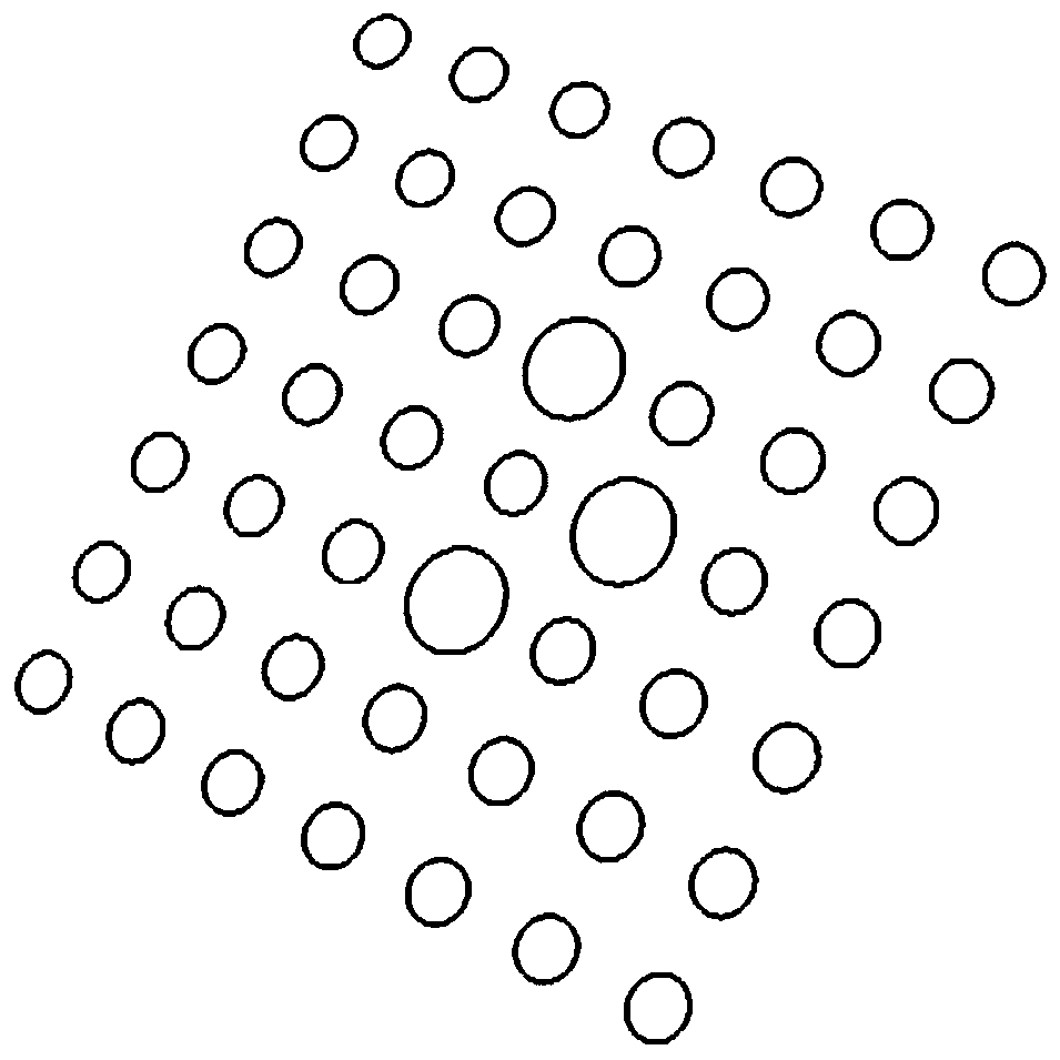
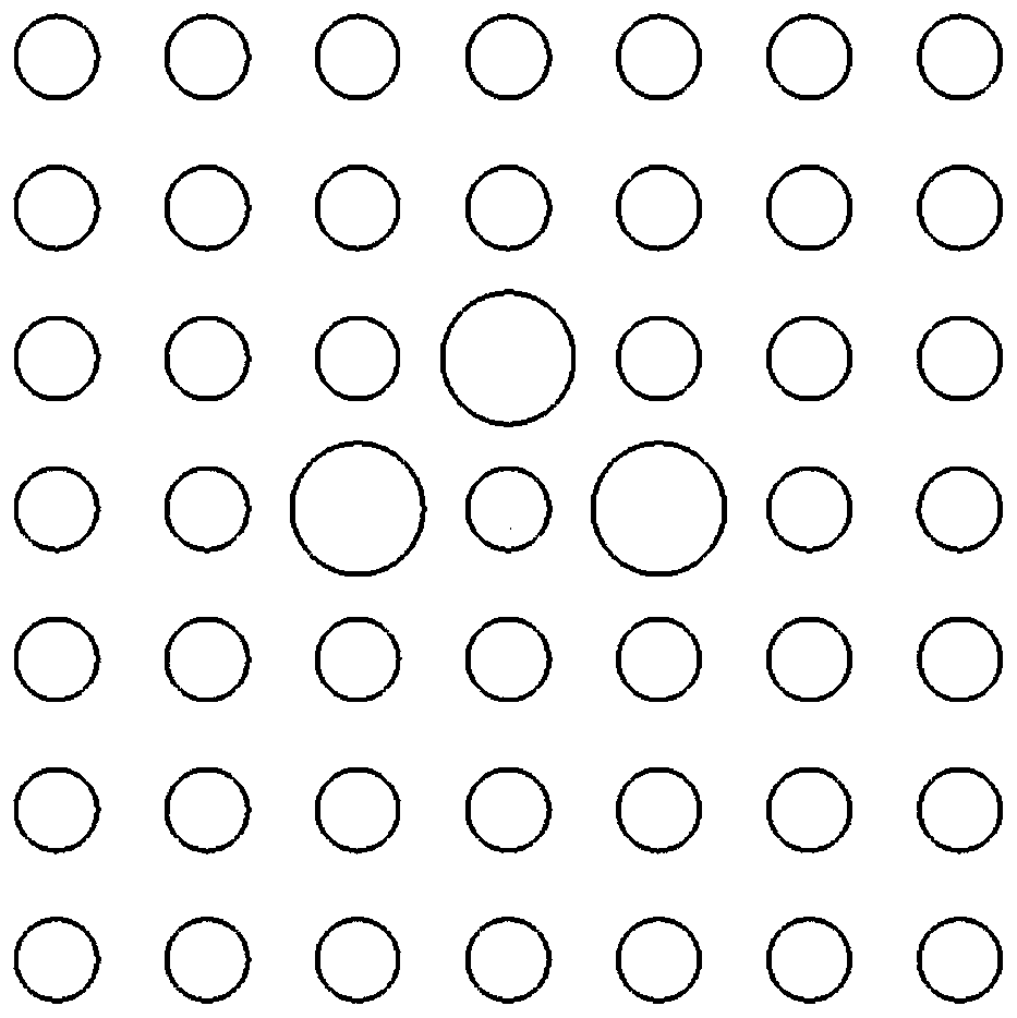
[0030] Embodiment 1 of the present invention provides a calibration board, see figure 1 As shown in the schematic diagram of the calibration board structure, the calibration board includes:

[0031] (1) The calibration board is a plane calibration board; the calibration board is provided with characteristic dots arranged in a matrix at equal intervals; the characteristic dots are all arranged inside the outer frame.

[0032] Set n rows and m columns of characteristic dots on the plane calibration board at equal intervals. The distance between adjacent circle centers can be set to 1 (the unit can be determined according to actual needs), and the dot radius is about 1 / 4. Feature dots can be printed on specific materials, such as paper, glass, ceramics, aluminum, film, etc. Different materials can have many different printing processes (such as photolithography, laser carving, light painting, laser printing, etc.).

[0033] The characteristic dots provide the most bas...

Example Embodiment

[0044] Example 2

[0045] Embodiment 2 of the present invention provides a method for identifying a calibration plate, see Figure 5 As shown in the schematic diagram of the flow chart of the calibration board identification method of the method, the method includes the following steps:

[0046] Step S502, acquiring a target image taken by the camera including the calibration plate as in Embodiment 1;

[0047] The camera may be a camera to be calibrated. The target image is an image including a complete calibration plate image as in Embodiment 1 or an image including a part of the calibration plate as in Embodiment 1. The part of the calibration plate may be a calibration plate whose edges are partially blocked.

[0048] Step S504: Determine the position of the calibration plate in the target image, and determine the estimated position of each dot in the calibration plate area and the position of the world coordinate system according to the marked characteristic dots;

[0049] The pos...

Example Embodiment

[0069] Example 3

[0070] Embodiment 3 of the present invention provides a calibration plate identification device, see Image 6 The shown schematic diagram of the structure of the calibration board identification device includes:


PUM


Abstract

The invention provides a calibration plate and a calibration plate identification method and device, and relates to the technical field of camera calibration, wherein the calibration plate is a planecalibration plate and is provided with feature dots which are arranged in n rows and m columns at equal intervals; the feature dots are arranged in the outer frame; the central area of the calibrationplate is provided with three mark feature round points; wherein the diameter of the mark feature dot is greater than that of the feature dot; wherein the three mark feature dots are not collinear, and any two mark feature dots are arranged in the same row in a non-adjacent manner and are arranged in the same column in a non-adjacent manner; touch round points are arranged at the circle centers ofthe characteristic round points of at least three vertexes of the calibration plate, and the radius of the touch round points is far smaller than that of the characteristic round points. The calibration precision can be optimized.

Description

technical field [0001] The invention relates to the technical field of camera calibration, in particular to a calibration board, a calibration board identification method and a device. Background technique [0002] Camera calibration is the basic link of machine vision applications such as visual measurement and 3D reconstruction. The accuracy and precision of the calibration results directly determine whether the vision system can work normally. Camera calibration refers to the process of using the camera system to capture the image of the calibration plate, using the three-dimensional coordinates of the known feature points in the calibration plate and the corresponding image coordinates on the image to solve the camera parameters. Camera calibration includes camera calibration data collection and camera parameter calculation. Most of the calibration plates used in camera calibration data acquisition are checkerboard and circular arrays. Among them, during the use of the...

Claims


Application Information

Patent Timeline
IPC IPC(8): G06T7/70G06T7/194G06T7/80
CPCG06T7/70G06T7/194G06T7/80G06T2207/10004
Inventor 崔坤黄耀孙超
Owner 北京阿丘机器人科技有限公司
Why Eureka
Try Eureka