
Organic electroluminescent device, display panel and display device

An electroluminescence device and a luminescence technology, which are applied in the direction of electric solid-state devices, electrical components, semiconductor devices, etc., can solve the problem that the recombination center of electrons and holes deviates from the center of the light-emitting layer, the difference in transport characteristics of electrons and holes, and light-emitting devices. Luminance attenuation and other issues to achieve the effect of reducing the risk of deterioration, reducing the attenuation of luminous brightness, and reducing the probability

Inactive Publication Date: 2019-08-20
BOE TECH GRP CO LTD
View PDF6 Cites 4 Cited by
  • Summary
  • Abstract
  • Description
  • Claims
  • Application Information

AI Technical Summary

Problems solved by technology

At present, there are some technical problems in the structure of organic electroluminescent devices. For example, due to the difference in the transport characteristics of electrons and holes in the light-emitting layer, the recombination center of electrons and holes will deviate from the center of the light-emitting layer.
When the electron and hole recombination centers are close to the interface of the electron blocking layer or the hole blocking layer, interface aging is more likely to occur at the interface, resulting in problems such as brightness attenuation and low current efficiency of organic electroluminescent devices.

Method used


Image

  • Organic electroluminescent device, display panel and display device
  • Organic electroluminescent device, display panel and display device
  • Organic electroluminescent device, display panel and display device

Examples


Embodiment Construction

[0022] In order to make the objectives, technical solutions and advantages of the present invention clearer, specific implementations of the organic electroluminescent device, display panel and display device provided by the embodiments of the present invention will be described in detail below with reference to the accompanying drawings.

[0023] The film thickness and shape of each layer in the drawings do not reflect the true ratio of the organic electroluminescent device, and the purpose is only to illustrate the content of the present invention schematically.

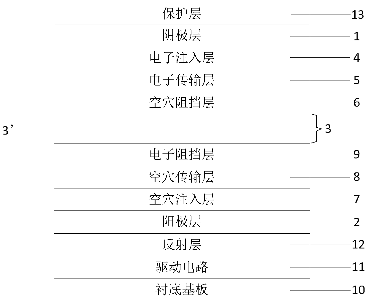
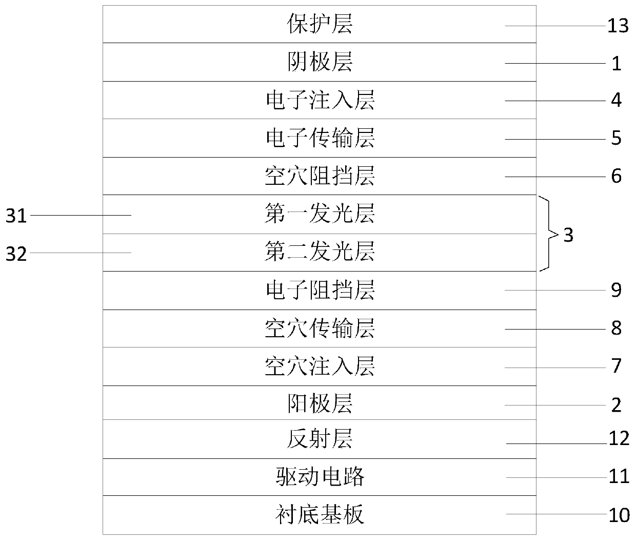
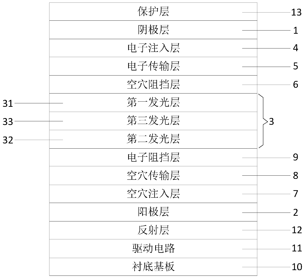
[0024] The organic electroluminescent device provided by the embodiment of the present invention, such as Figure 1 to Figure 3 As shown, it includes: a cathode layer 1 and an anode layer 2 arranged oppositely, and a light-emitting composite structure 3 located between the cathode layer 1 and the anode layer 2; the light-emitting composite structure 3 is mixed with hole-type materials, electronic-type materials and lumin...


PUM

PropertyMeasurementUnit
Thicknessaaaaaaaaaa
Thicknessaaaaaaaaaa

Abstract

The invention discloses an organic electroluminescent device, a display panel and a display device. The proportion of an electronic material close to a cathode layer in a luminescent composite structure of the organic electroluminescent device is larger than that of a hole type material, the proportion of the hole type material close to the anode layer in the luminescent composite structure is larger than that of the electronic material, when a light-emitting layer emits light, electrons in the cathode layer can be easily transmitted to the side, close to the cathode layer, of the luminescentcomposite structure and holes in the anode layer can be easily transmitted to the side, close to the anode layer, of the luminescent composite structure, thereby ensuring that the recombination position of the electrons and the holes is controlled in the luminescent composite structure, avoiding quenching caused by the diffusion of the electrons and the hole to other layers, reducing the probability that the recombination position of the electrons and the holes deviates to the interface of a barrier layer, reducing the risk of degradation at the interface of the barrier layer and improving thebalance capability of current carriers in the organic electroluminescent device, and therefore, the luminance attenuation is reduced, and the current efficiency is improved.

Description

Technical field [0001] The invention relates to the field of display technology, in particular to an organic electroluminescent device, a display panel and a display device. Background technique [0002] Organic light emitting diodes (Organic Light Emitting Diode, OLED) are highly valued in the field of flat panel display and lighting due to their advantages of high brightness, saturated color, thinness, and flexibility. [0003] In the structure of an organic electroluminescence device, electrons and holes are injected from the cathode and the anode, respectively, and emit light in the light-emitting layer of the device. Therefore, the number of electrons and holes transported to the light-emitting layer plays an important role in the performance of the organic electroluminescent device. At present, there are some technical problems in the structure of organic electroluminescent devices. For example, due to the difference in the transport characteristics of electrons and holes in...

Claims


Application Information

Patent Timeline
IPC IPC(8): H01L51/50H01L51/56
CPCH10K50/13H10K50/11H10K71/00
Inventor 吴海东李彦松
Owner BOE TECH GRP CO LTD
Learn More