
Laser cutting working platform

A working platform and laser cutting technology, which is applied in laser welding equipment, manufacturing tools, metal processing equipment, etc., can solve the problems of ignoring positioning, reducing production efficiency, and increasing the scrap rate of workpieces, so as to achieve precise cutting, improve production efficiency, Effect of reducing workpiece rejection rate

Pending Publication Date: 2019-08-23
河南力锋科技有限公司 +1
View PDF3 Cites 7 Cited by
  • Summary
  • Abstract
  • Description
  • Claims
  • Application Information

AI Technical Summary

Problems solved by technology

The technology disclosed above realizes the automatic feeding and cutting of laser cutting, and also takes into account the positioning of the plate on the cutting machine; , will lead to an increase in the scrap rate of the workpiece during the cutting process, and the untimely delivery of the plate after cutting will also reduce the production efficiency. For example, the laser cutting flexible line system disclosed by Chen Dong (201310257979.6) ignores the positioning problem during the moving cutting process of the plate

Method used


Image

  • Laser cutting working platform
  • Laser cutting working platform
  • Laser cutting working platform

Examples


Embodiment approach 1

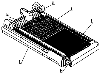
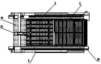
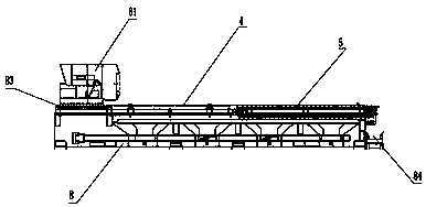
[0039] The laser cutting working platform of the present invention is as Figure 1-3 As shown, a main bed 8 is provided and a clean material cutting area 4 and a rotating table 5 are provided from back to front, and the clean material cutting area 4 and the rotating table 5 are fixed together on the main bed 8 of the laser cutting work platform , the main bed 8 is also provided with a laser cutting head assembly 81, the laser cutting head assembly 81 is placed above the clean material cutting area 4 and the rotating table 5; during specific implementation, the laser cutting head assembly 81 can move;

[0040] Such as Figure 4-5 with Figure 8 As shown, the clean material cutting area 4 is provided with more than two clean material cutting support strips 41, a clean material cutting servo motor 42 and a stop mount; the left and right ends of the stop mount are bolted to the main bed 8 On the top, there are two stop mounts arranged symmetrically along the longitudinal direct...


PUM


Abstract

The invention belongs to the technical field of laser cutting production equipment for sheet metal production, and particularly relates to a laser cutting working platform. The laser cutting working platform is provided with a main lathe bed (8) and is provided with a net material cutting area (4) and a rotating workbench (5) from back to front, and the net material cutting area (4) and the rotating workbench (5) are fixed to the main lathe bed (8) jointly; the net material cutting area (4) is provided with a plurality of net material cutting supporting strips (41), a net material cutting servo motor (42) and a stopping mounting base; and the rotating workbench (5) is provided with a plurality of rotating supporting strips (51), a rotating servo motor (52), a chain supporting rail (53) anda supporting bracket (54). According to the laser cutting working platform, the net material cutting area and the rotating workbench are arranged on the main lathe bed, so that a plate is subjected to net material cutting firstly in the accurate positioning of the net material cutting area, then the plate is conveyed to the rotating workbench to complete cutting of a workpiece, automatic blankingis realized, and the production efficiency is improved.

Description

technical field [0001] The invention belongs to the technical field of laser cutting production for sheet metal production, and in particular relates to a laser cutting work platform, which is suitable for laser cutting various plates to produce workpieces with different geometric shapes. Background technique [0002] Laser cutting machine is the equipment used for cutting and blanking in the sheet metal processing industry. In recent years, because of its fast cutting speed and high production efficiency; good cutting quality, narrow slit, and no tool wear, no matter it is simple or complex parts, it can The advantages of using laser one-time precision rapid prototyping and cutting have been rapidly popularized and applied in the field of sheet metal processing. [0003] During the laser cutting process, the plate is cut by the laser cutting head. First, the entire plate is transported to the cutting machine. After the entire plate to be cut is fixed, the laser cutting head...

Claims


Application Information

Patent Timeline
IPC IPC(8): B23K26/38B23K26/70
CPCB23K26/38B23K26/702
Inventor 赵世辉
Owner 河南力锋科技有限公司
Learn More