Automatic sectional material cutting production equipment and method

A technology for automatic cutting and production equipment, applied in workshop equipment, welding equipment, metal processing equipment, etc., can solve the problems of high maintenance and processing costs, poor quality, and difficult processing of complex wedge-head workpieces, etc., to reduce labor intensity and transport And the effect of reasonable connection and clear and orderly rhythm of work

Active Publication Date: 2019-08-23
北京林克曼数控技术股份有限公司
View PDF8 Cites 29 Cited by
  • Summary
  • Abstract
  • Description
  • Claims
  • Application Information

AI Technical Summary

Problems solved by technology

[0007] In view of the above analysis, the present invention aims to provide a profile automatic cutting production equipment and method to solve the problems of low efficiency, poor quality, high maintenance and processing costs, and difficult processing of complex wedge workpieces in the prior art.

Method used


Image

  • Automatic sectional material cutting production equipment and method
  • Automatic sectional material cutting production equipment and method
  • Automatic sectional material cutting production equipment and method

Examples


Embodiment 1

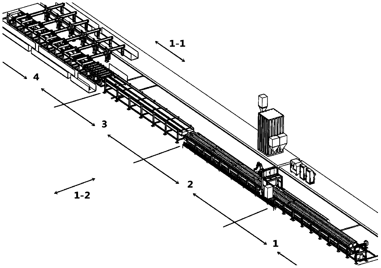
[0058] Such as figure 1 As shown, an automatic profile cutting production equipment adopts a rotary chain plate to transfer workpieces. The layout of the main functional work area includes: X-axis vertical 1-1, Y-axis horizontal 1-2, material spraying area 1, cutting area 2 , to be sorted area 3 and unloading area 4.

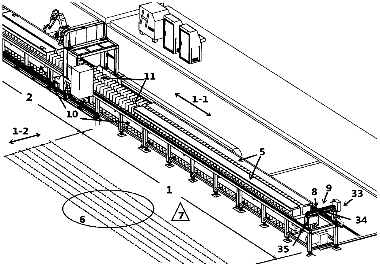
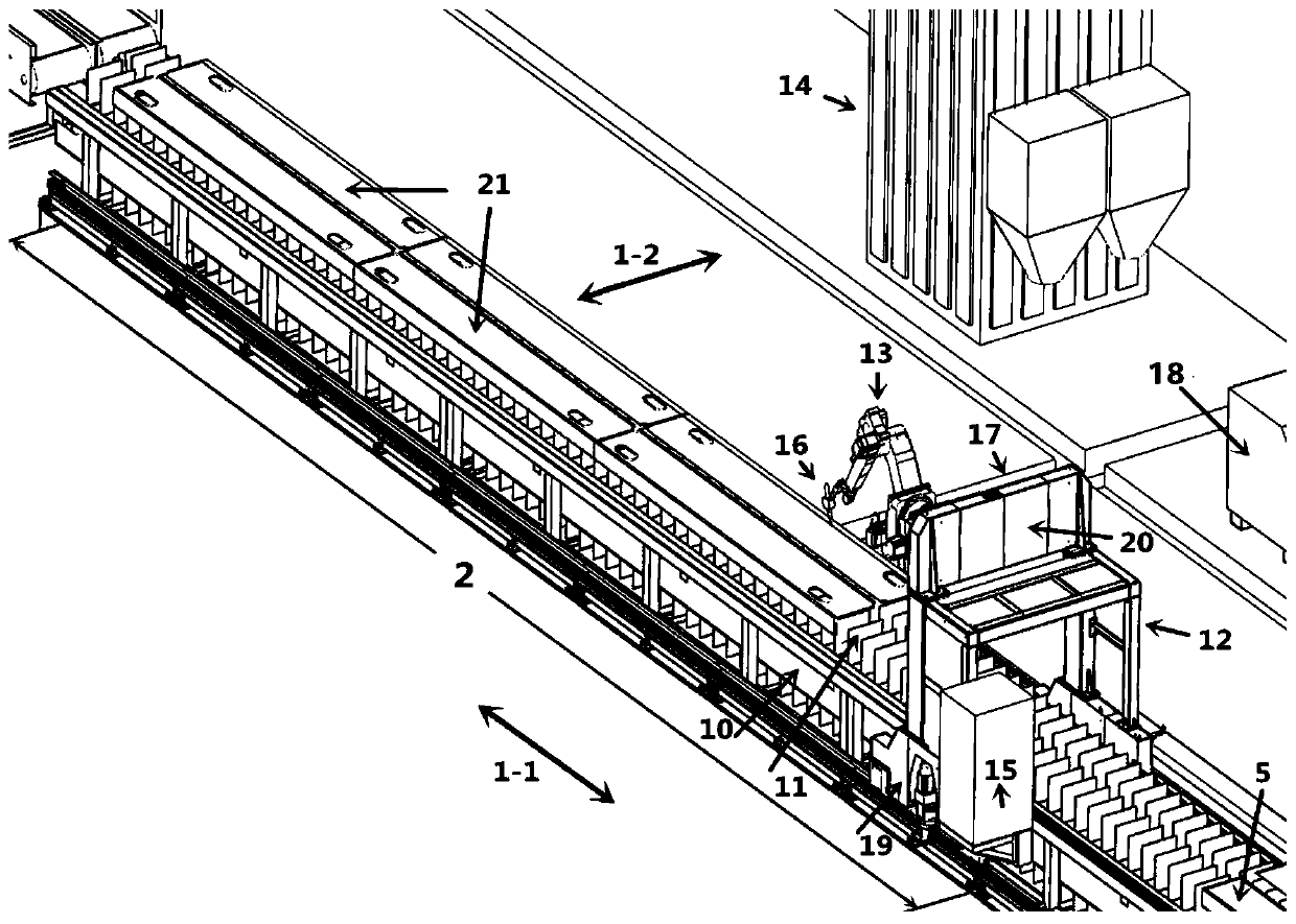
[0059] Such as figure 2 , 3 As shown, the feeding coding area 1 and the cutting area 2 jointly use a set of rotary chain plate transmission mechanism 10 and two sets of parallel material tables 11 to complete the transmission, coding, scribing and cutting of two sets of profile raw materials 5 .

[0060] Such as Figure 4 As shown, the area to be sorted 3 has adopted two sets of second rotary chain plate transmission mechanisms 22 arranged in parallel, and a waste collection vehicle 23 arranged at the lower end of the gap between the area to be sorted 3 and the cutting area 2, and the area to be sorted The sorting area 3 is mainly responsible for completing...

Embodiment 2

[0080] A profile automatic cutting method, using the above profile automatic cutting production equipment, comprising the following steps:

[0081]S1. Place the two profile raw materials 5 from the profile buffer storage area 6 to the two sets of parallel material tables 11 in the loading and coding area 1 through the combined electro-permanent magnet spreader 7, start the laser measurement and control and coding and scribing procedures, and install The coding and scribing device 8 and the laser measurement and control device 9 on the plotter 33 automatically complete the deformation measurement and control and coding and scribing operations of two groups of profile materials;

[0082] S2. Start the automatic cutting program, the first rotary chain plate workpiece transmission mechanism 10 transfers the two groups of profile materials 5 that have completed the coding and scribing operation to the cutting area 2, and the cutting robot body 13 cuts the profile materials 5 to obta...


PUM


Abstract

The invention discloses automatic sectional material cutting production equipment and a method. The equipment solves the problem that the efficiency is low, the quality is poor, the maintenance and machining cost is high, the machining difficulty of a complex wedge-head workpiece is high when cutting workpieces in the prior art. The production equipment comprises a feeding and code inkjet printingarea (1), a cutting area (2), a to-be-sorted area (3) and a discharging area (4), the feeding and code inkjet printing area (1), the cutting area (2), the to-be-sorted area (3) and the discharging area (4) are arranged in sequence, the the feeding and code inkjet printing area (1) and the cutting area (2) are provided and a first rotary type chain plate conveying mechanism (10) and a material table (11), the to-be-sorted area (3) is provided with two sets of second rotary type chain plate conveying mechanisms (22) which are arranged in parallel, and the discharging area (4) is provided with adischarging mechanism longitudinal conveying roller set device (24) and a discharging mechanism transverse rotating chain moving device (25). According to the equipment and the method, the efficiencyof cutting the workpiece is greatly improved.

Description

technical field [0001] The invention belongs to the technical field of profile cutting, in particular to a profile automatic cutting production equipment and method. Background technique [0002] Usually, the common profile workpiece processing equipment in the market is mainly cold processing machine tools, such as sawing machines, milling machines and drilling machines. The main functions of profile workpiece processing equipment are sawing machine cutting to length, milling machine lock or milling welding groove, drilling machine hole processing and other processes. Due to objective factors such as slow processing speed of cold processing machine tools, many types of tool replacement, long time for sharpening and setting tools, and repeated and continuous conversion of processes, it can no longer adapt to the current steel structure, glass curtain wall, shipbuilding, ocean engineering, rail transit, and heavy vehicles. , construction machinery, warehousing and logistics,...

Claims


Application Information

Patent Timeline
Patent Type & Authority Applications(China)
IPC IPC(8): B23P23/06B23K10/00B25H7/04B23Q7/00B23Q17/20B23Q17/24
CPCB23K10/00B23P23/06B23Q7/00B23Q17/20B23Q17/2471B25H7/04
Inventor 陆元元刘旭超刘宝洲李学林朱涛杨丽郭晴王瀚王复海梁晓东
Owner 北京林克曼数控技术股份有限公司
Why Eureka
Try Eureka