

All-directional movable double-arm robot
An omnidirectional mobile and robotic technology, applied in the field of omnidirectional mobile dual-arm robots, can solve the problems of limited working space and many blind spots of omnidirectional mobile dual-arm robots, and achieve the goal of solving the singleness problem, improving the operating space and compacting the device Effect
- Summary
- Abstract
- Description
- Claims
- Application Information
AI Technical Summary
Problems solved by technology
Method used
Image

Examples
Embodiment 1
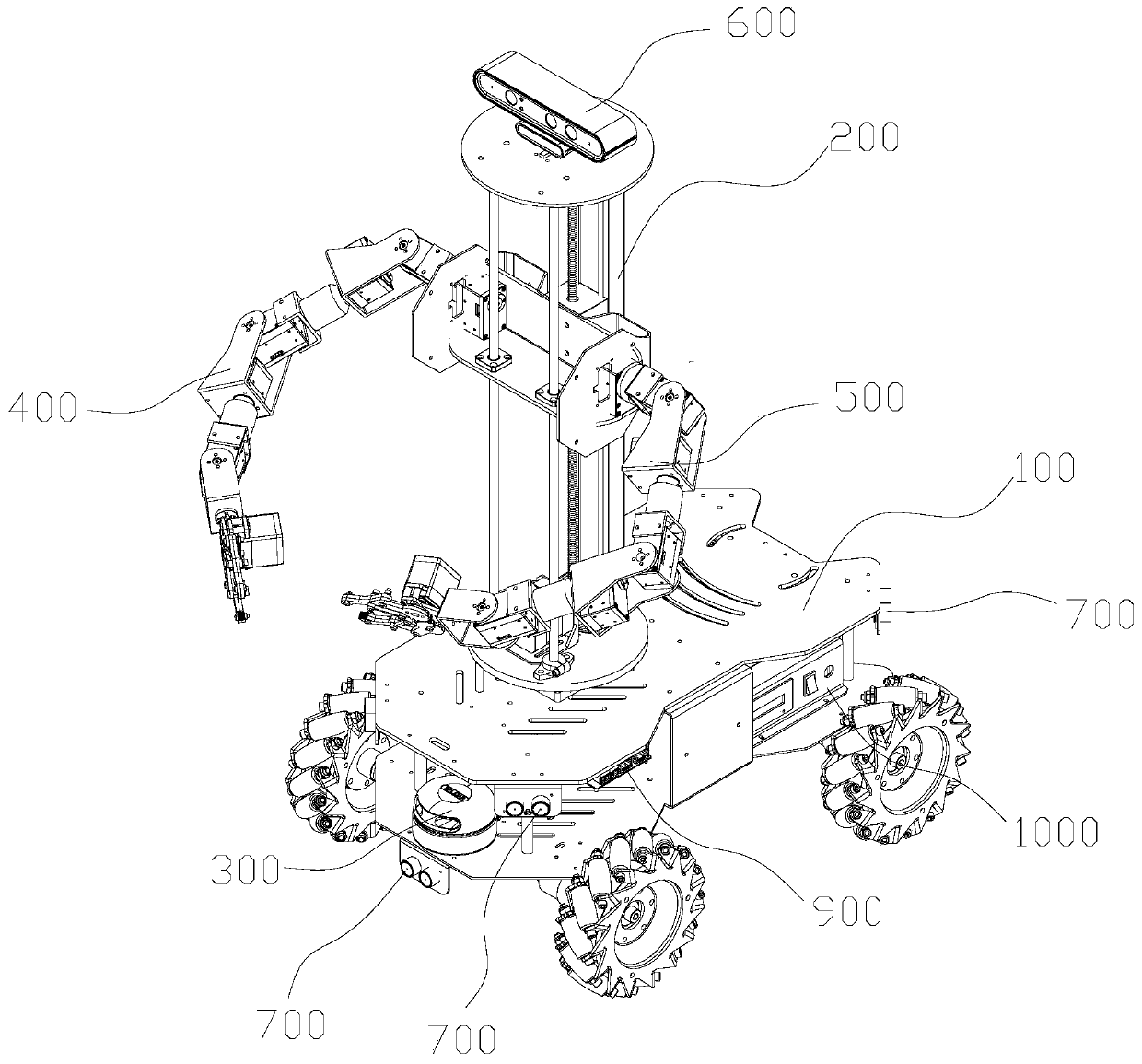
[0039] Such as figure 1 , 2 shown, combined with Figure 3-5 In this embodiment, the omnidirectional mobile dual-arm robot includes a car body 100, a rotary lifting platform 200, a laser radar 300, a first robotic arm 400, a second robotic arm 500, a camera 600, a plurality of ultrasonic sensor modules 700, and a power supply system 800 , embedded host 900, industrial control host 1000;
[0040] The rotary lifting platform 200 is rotatably installed on the top surface of the car body 100, the laser radar 300 is rotatably installed on the top of the rotary lifting platform 200, and the first mechanical arm 400 and the second mechanical arm 500 are rotatably installed on the rotary lifting platform. 200 on;
[0041] The embedded host 900, the camera 600 and the laser radar 300 are respectively electrically connected to the industrial control host 1000;
[0042] The motor on the vehicle body 100, the first mechanical arm 400, the second mechanical arm 500, and a plurality of ul...
Embodiment 2
[0051] The difference between the second embodiment and the first embodiment is that the specific structure of the rotary lifting platform 200 is refined.
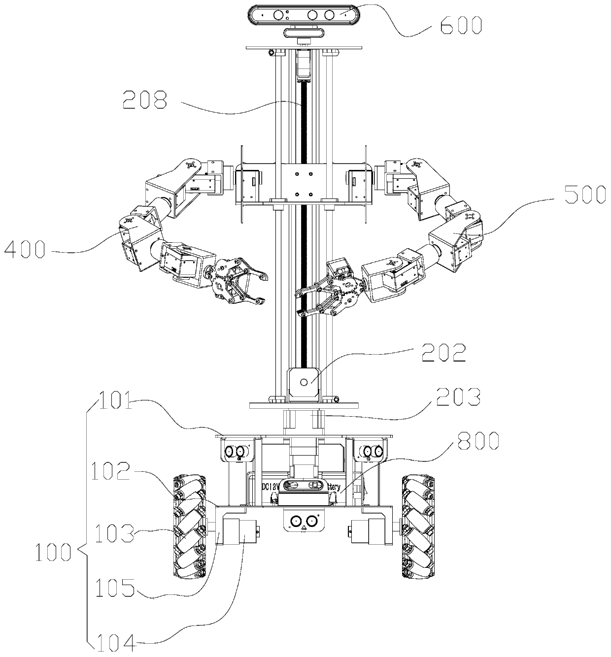
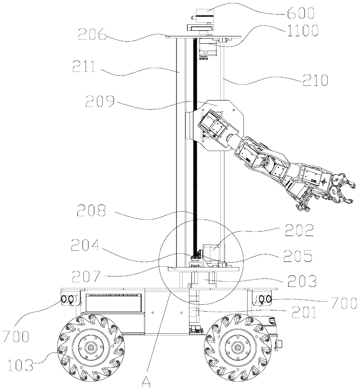
[0052] Such as Figure 1-5 As shown, the rotary lifting platform 200 includes a base, a first motor 201, a second motor 202, a hollow rotating platform 203, a first bevel gear 204, and a second bevel gear 205, wherein the base includes a first A rotary table 206, a second rotary table 207, a linear guide rail 208, and a slider 209. The second rotary table 207 is installed on the hollow rotary platform 203, and the hollow rotary platform 203 is installed on the top plate 101. The first motor 201 is driven to connect the hollow rotary platform. platform 203, the first motor 201 is installed on the bottom surface of the top plate 101, the first bevel gear 204 is fixed on the second turntable 207, the second motor 202 is installed horizontally on the second turntable 207, the second bevel gear 205 It is also installed horizon...
Embodiment 3
[0057] The difference between embodiment three and implementation two is:
[0058] Such as Figure 1-5 As shown, in this embodiment, a steering gear 1100 is also included. The steering gear 1100 is installed on the top of the first turntable 206 . The steering gear 1100 drives and connects to the camera 600 . The steering gear 1100 is a servo steering gear that can realize the 360° rotation of the camera 600. The 360-degree rotation movement of the 3D depth camera fixed at the end of the steering gear 1100 can effectively improve the imaging angle of the 3D depth camera to adapt to more application environments. Reality.
PUM
 Abstract
Description
Claims
Application Information