Supporting plate lifting device for mold shell chain injection machine

A technology of chain injection machine and pallet, which is applied in the direction of conveyor objects, transportation and packaging, etc., which can solve the problems of difficult production, increased equipment cost, and large frictional resistance, so as to increase the ability to flexibly carry pallets and reduce equipment loss , The effect of increased seismic performance

Inactive Publication Date: 2019-08-23
烟台政通节能建材设备制造有限公司
View PDF0 Cites 2 Cited by
  • Summary
  • Abstract
  • Description
  • Claims
  • Application Information

AI Technical Summary

Problems solved by technology

[0002] The supporting plate lifting device of the formwork chain injection machine adopts two hydraulic cylinders to lift simultaneously on both sides. Due to the difference in lifting resistance, the lifting of the supporting plate sometimes cannot guarantee the horizontal lifting and synchronous lifting
Eight cylinders are used for the left and right positioning of the pallet stack, and the eight cylinders control the falling and raising of the eight supporting legs. The control is complicated, the gas consumption is large, and the production is difficult, which increases both the equipment cost and the use cost.
Due to the large frictional resistance between the pallets in the pallet stack and the limited power of the cylinder to control the mopping feet, the left and right positioning of the pallet stack is not very ideal, making it difficult to pick up the pallets

Method used


Image

  • Supporting plate lifting device for mold shell chain injection machine
  • Supporting plate lifting device for mold shell chain injection machine
  • Supporting plate lifting device for mold shell chain injection machine

Examples


Embodiment Construction

[0023] The principles and features of the present invention are described below in conjunction with the accompanying drawings, and the examples given are only used to explain the present invention, and are not intended to limit the scope of the present invention.

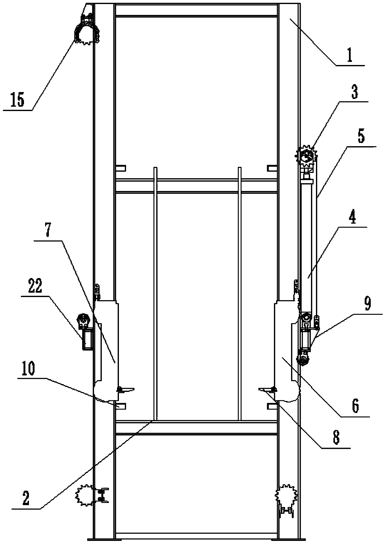
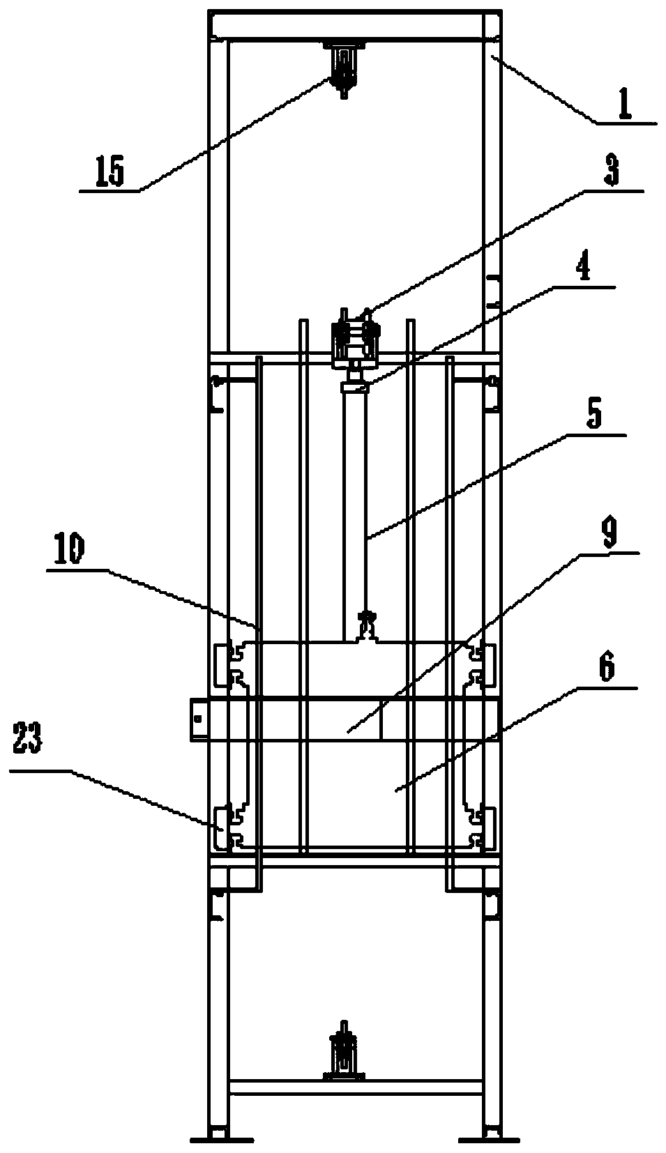
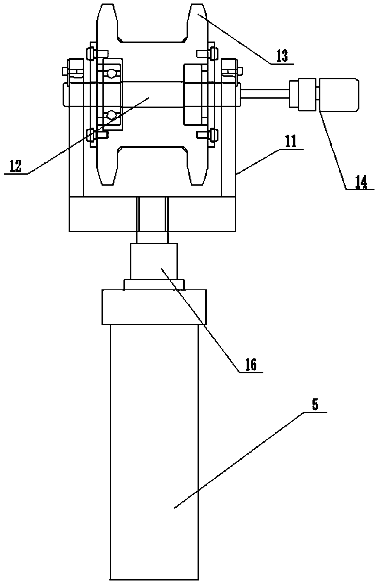
[0024] A pallet lifting device for a formwork chain injection machine, comprising a lifting frame 1 and a pallet stack 2, the pallet stack 2 is located at the bottom of the lifting frame 1, and both sides of the lifting frame 1 are connected with a double sprocket assembly 3 and a driven sprocket assembly , the hydraulic cylinder 4 is installed on the side of the lifting frame 1, the hydraulic cylinder 4 is connected with the double sprocket assembly 3, the double sprocket assembly 3 is connected with the sleeve roller chain 5, and the sleeve roller chain 5 and the double sprocket assembly 3 pass through the sleeve The roller chain 5 is connected to the lifting trolley Ⅰ6 by transmission, and the sleeve roller chain ...


PUM


Abstract

The invention relates to a supporting plate lifting device and particularly relates to a supporting plate lifting device for a mold shell chain injection machine, and belongs to the technical field ofproduction of building materials by utilizing a modified cement polystyrene particle material. The supporting plate lifting device comprises a hoisting frame and a supporting plate stack, wherein thesupporting plate stack is located at the bottom of the hoisting frame; two sides of the hoisting frame are connected with a double-chain-wheel assembly and a driven chain wheel assembly; a hydrauliccylinder is mounted on a side face of the hoisting frame; the hydraulic cylinder is connected with the double-chain-wheel assembly; the double-chain-wheel assembly is connected with a sleeve roller chain; the sleeve roller chain is in transmission connection with the double-chain-wheel assembly through the sleeve roller chain and a hoisting trolley I; the sleeve roller chain penetrates through thedriven chain wheel assembly to be in transmission connection with a hoisting trolley II; and the hoisting trolley I and the hoisting trolley II are located on the same horizontal plane of the hoisting frame. The supporting plate lifting device provided by the invention has the beneficial effects that the hoisting trolleys are operated synchronously and horizontally and stable operation of a supporting plate is ensured; one supporting plate is picked through a picking device after the picking device reaches a supporting plate picking position; and then the supporting plate is jacked through the hydraulic cylinder and the other supporting plate is picked.

Description

technical field [0001] The invention relates to a pallet elevating device, in particular to a pallet elevating device for a form shell chain injection machine, which belongs to the technical field of producing building materials by using modified cement polystyrene granular materials. Background technique [0002] The supporting plate lifting device of the formwork chain injection machine adopts two hydraulic cylinders to lift at the same time on both sides. Due to the difference in lifting resistance, the lifting of the supporting plate sometimes cannot guarantee horizontal lifting and synchronous lifting. Eight air cylinders are used for the left and right positioning of the pallet stack, and the eight air cylinders control the falling and lifting of the eight supporting legs. The control is complicated, the air consumption is large, and the production is difficult, which increases both the equipment cost and the use cost. Due to the large frictional resistance between the...

Claims


Application Information

Patent Timeline
Patent Type & Authority Applications(China)
IPC IPC(8): B65G47/74
CPCB65G47/74
Inventor 王涛隋群解泽宇王琳姜美仙王建东邵子洪常宁王锡强解华张彩霞邵云波
Owner 烟台政通节能建材设备制造有限公司
Why Eureka
Try Eureka