
Foundation of power distribution equipment building of prefabricated transformer substation and construction method

A technology of power distribution device and construction method, which is applied in basic structure engineering, construction and other directions, can solve the problems of long construction time and poor construction environment of the power distribution device building of substations, and achieves accelerated production and use time, good construction quality, and construction. handy effect

Pending Publication Date: 2019-08-23
STATE GRID ZHEJIANG ELECTRIC POWER CO LTD JINHUA POWER SUPPLY CO +2
View PDF0 Cites 2 Cited by
  • Summary
  • Abstract
  • Description
  • Claims
  • Application Information

AI Technical Summary

Problems solved by technology

[0003] The purpose of the present invention is to provide a foundation and construction method for a prefabricated substation power distribution device building, which can effectively solve the problems of long construction time and poor construction environment of the existing substation power distribution device building

Method used


Image

  • Foundation of power distribution equipment building of prefabricated transformer substation and construction method
  • Foundation of power distribution equipment building of prefabricated transformer substation and construction method
  • Foundation of power distribution equipment building of prefabricated transformer substation and construction method

Examples


Embodiment Construction

[0030] Embodiments of the invention are described in detail below, examples of which are illustrated in the accompanying drawings. The embodiments described below by referring to the figures are exemplary and are intended to explain the present invention and should not be construed as limiting the present invention.

[0031] In describing the present invention, it should be understood that the terms "center", "longitudinal", "transverse", "length", "width", "thickness", "upper", "lower", "front", " The orientation or positional relationship indicated by "rear", "left", "right", "vertical", "horizontal", "top", "bottom", "inner" and "outer" are based on the orientation or position shown in the drawings The positional relationship is only for the convenience of describing the present invention and simplifying the description, but does not indicate or imply that the referred device or element must have a specific orientation, be constructed and operated in a specific orientation,...


PUM


Abstract

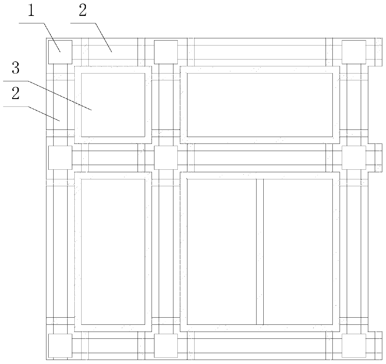
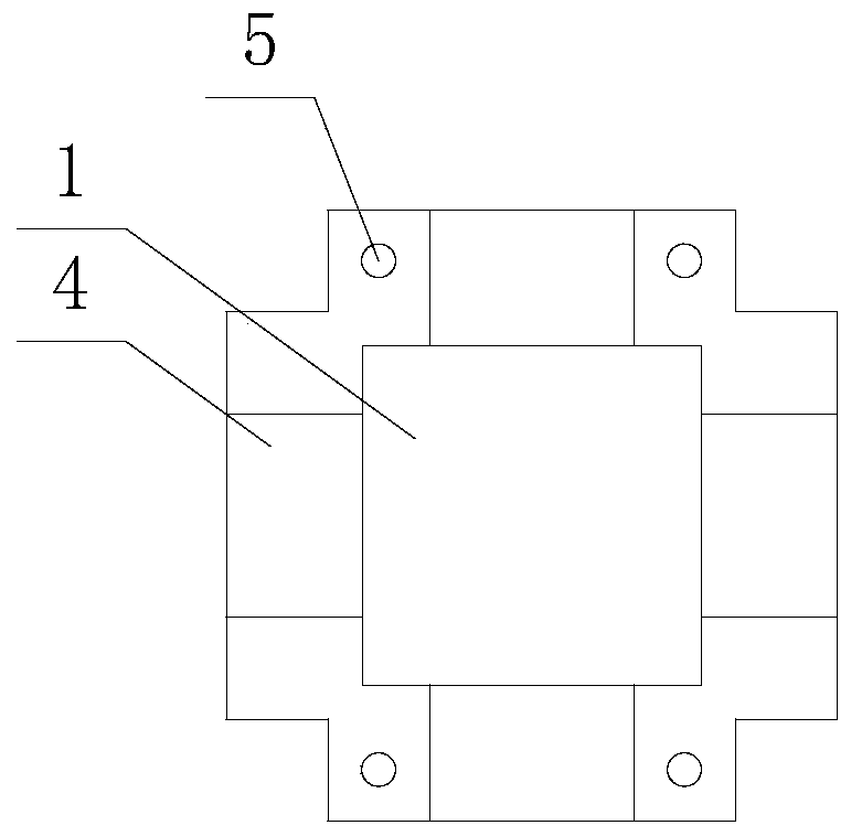
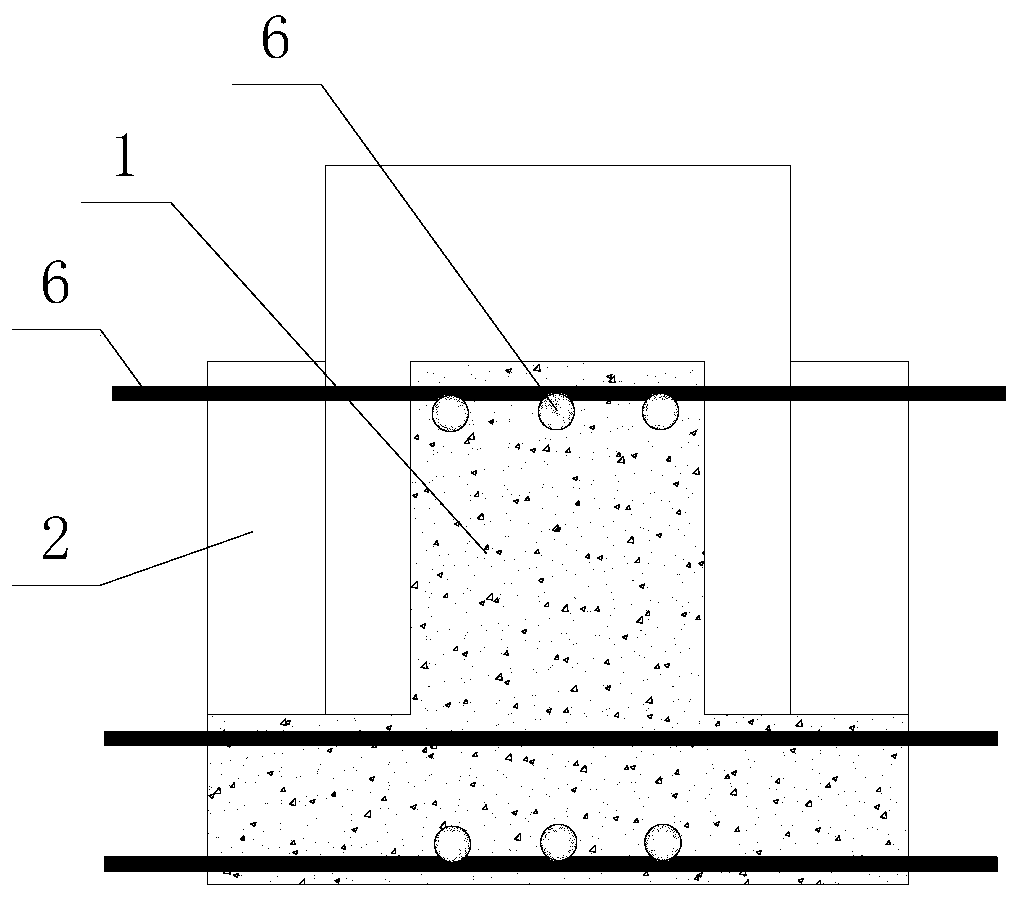
The invention discloses a foundation of a power distribution equipment building of a prefabricated transformer substation. The foundation comprises two stubs, a grade beam and a bottom plate. Liftingplatforms are arranged on the side walls of the stubs, adjusting holes are formed in the lifting platforms, two ends of the grade beam are separately arranged on lifting platforms of the stubs, the bottom plate is arranged on the grade beam, a leveling device is arranged in each adjusting hole, reinforcing steel bars are arranged on the stubs and the grade beam, after the grade beam is arranged onthe lifting platforms, and the reinforcing steel bars on the grade beam are fixedly connected to the reinforcing steel bars on the stubs. The construction method comprises the following steps: excavating the foundation; then putting the stubs in the foundation and leveling the stubs; putting the grade beam and the bottom plate; then carrying out welding and fixing; and finally, casting concrete.The foundation has the advantages that as the upper structure and equipment of the power distribution equipment building are carried out in a standardized manner and the sizes and positions of the upper structure and an equipment load are relatively fixed, the structure and equipment foundation of the power distribution equipment building can be arranged in a standardized manner, so that convenience is brought to production of prefabricated parts on a large scale; the prefabricated foundation can lower the design and on-site production cost and is convenient to construct.

Description

technical field [0001] The invention relates to a foundation and a construction method of a prefabricated substation power distribution device building. Background technique [0002] With the improvement of people's living standards, the power consumption of daily life and production is increasing. In order to meet the requirements of power transmission, more substations need to be built. At present, most of the upper structure of the power distribution device of the substation adopts steel structure, and the lower foundation adopts cast-in-place reinforced concrete foundation. The construction time of cast-in-place reinforced concrete foundation is long, and the construction environment is poor, which will have a great impact on the surrounding environment and people's lives. Contents of the invention [0003] The object of the present invention is to provide a foundation and construction method for a prefabricated substation power distribution device building, which can ...

Claims


Application Information

Patent Timeline
Patent Type & Authority Applications(China)
IPC IPC(8): E02D27/00E02D15/02
CPCE02D27/00E02D15/02
Inventor 朱云祥陈哲袁建国施首健屠锋陈崇敬柳毅杨杰刘锡成龚坚刚高亚栋俞辰颖方瑜吴祖咸金国胜尹康
Owner STATE GRID ZHEJIANG ELECTRIC POWER CO LTD JINHUA POWER SUPPLY CO
Learn More