
Engine combined cooling device and working method thereof

A cooling device and engine technology, applied in the direction of engine components, machine/engine, engine cooling, etc., to achieve the effect of reducing power loss

Inactive Publication Date: 2019-08-23
YANCHENG INST OF IND TECH
View PDF7 Cites 4 Cited by
  • Summary
  • Abstract
  • Description
  • Claims
  • Application Information

AI Technical Summary

Problems solved by technology

[0003] Aiming at the deficiencies of the prior art, the object of the present invention is to provide an engine combined heat sink and its working method to solve the problem in the prior art that the cooling fan can only be cooled by high-speed rotation

Method used


Image

  • Engine combined cooling device and working method thereof
  • Engine combined cooling device and working method thereof
  • Engine combined cooling device and working method thereof

Examples


Embodiment Construction

[0038] The present invention will be further described below in conjunction with the accompanying drawings. The following examples are only used to illustrate the technical solution of the present invention more clearly, but not to limit the protection scope of the present invention.

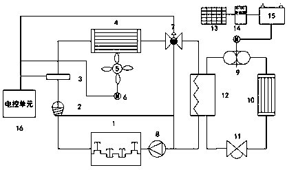
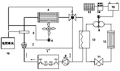
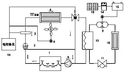
[0039] Such as figure 1 As shown, a combined heat dissipation device for an engine includes a thermostat 2, a temperature sensor 3, a radiator 4, a radiator fan 5, a fan motor 6, a temperature control valve 7, a water pump 8, a compressor 9, a condenser 10, an expansion Valve 11 , ice storage device 12 , photovoltaic cell 13 , motor 14 , storage battery 15 , and electronic control unit 16 .

[0040] The thermostat 2 is directly installed on the cylinder body of the engine 1 relying on the thermostat seat, the temperature sensor 3 is directly arranged on the thermostat seat, the lower part of the thermostat 2 is directly connected to the water pump 8 through a hose, and the water pump 8 is The ...


PUM


Abstract

The invention discloses an engine combined cooling device, and belongs to the field of car manufacture. The engine combined cooling device comprises an auxiliary cooling system, wherein the auxiliarycooling system comprises a compressor, a condenser, an expansion valve, an ice storage device, a photovoltaic cell and a motor compressor; one end of the ice storage device is connected with the compressor; the other end of the ice storage device is connected with the expansion valve; the compressor and the expansion valve are simultaneously connected with the condenser; the ice storage device isconnected with a water outlet and a water inlet of a water jacket in an engine; and the compressor is connected with the motor compressor. The engine combined cooling device provided by the inventionsolves the problems that cooling can be only realized through a cooling fan at present and machine shutdown is caused by insufficient cooling of the engine at a high-temperature area, and the power loss of the engine is reduced. The invention further discloses a working method of the engine combined cooling device.

Description

technical field [0001] The invention belongs to the field of vehicle manufacturing, and in particular relates to an engine combined cooling device and a working method thereof. Background technique [0002] Long-term operation of construction machinery in high-temperature areas such as deserts will cause insufficient heat dissipation of the engine and cause boiling. The boiling of the engine will cause the following consequences to the engine. The temperature of the parts is too high, which will significantly reduce the mechanical properties of the metal material, resulting in deformation and damage. The normal gap between the various parts will be destroyed due to the thermal expansion of the parts, so that the parts cannot work normally. The viscosity of the engine oil will become thinner or even oxidized and deteriorated, reducing the lubrication effect and aggravating the wear of parts. The traditional cooling system can only meet the heat dissipation requirements of th...

Claims


Application Information

Patent Timeline
IPC IPC(8): F01P9/06F01P5/10F01P5/04F01P7/16
CPCF01P5/04F01P5/10F01P7/16F01P9/06F01P2005/046F01P2007/146
Inventor 祁淼朱璟顾伟璐焦贝贝袁媛
Owner YANCHENG INST OF IND TECH
Learn More