
Isolator reverse power withstand test system and method

A technology of reverse power and test system, which is applied in the aerospace field, can solve the problems of unreliable test results of reverse power withstand test, and achieve the effect of reliable test method and reliable test result

Active Publication Date: 2021-03-02
上海中科辰新卫星技术有限公司
View PDF11 Cites 0 Cited by
  • Summary
  • Abstract
  • Description
  • Claims
  • Application Information

AI Technical Summary

Problems solved by technology

[0005] The purpose of the present invention is to provide a reverse power withstand test system and method of an isolator to solve the problem of unreliable test results of the existing reverse power withstand test

Method used


Image

  • Isolator reverse power withstand test system and method
  • Isolator reverse power withstand test system and method
  • Isolator reverse power withstand test system and method

Examples


Embodiment 1

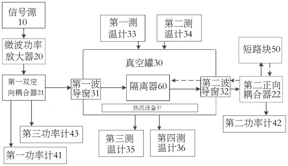
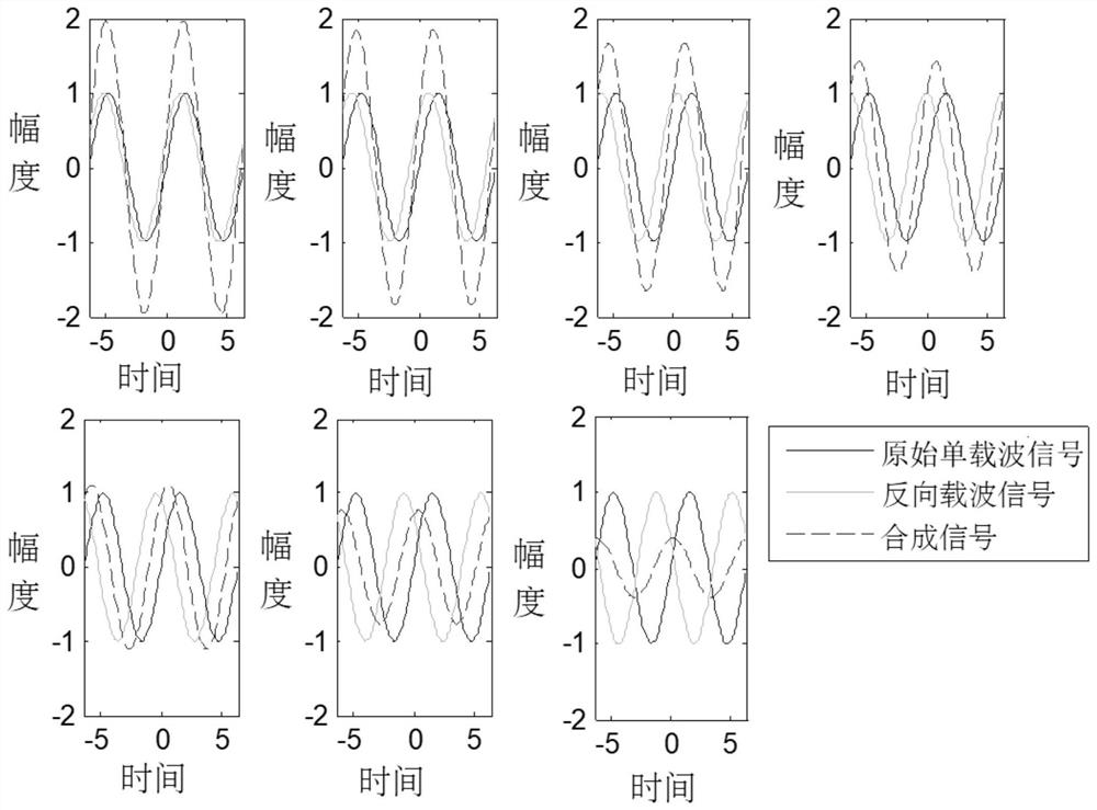
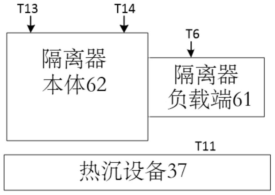
[0083] This embodiment provides an isolator reverse power withstand test system, such as figure 1 As shown, the isolator reverse power withstand test system includes a signal source 10, a microwave power amplifier 20, a first dual directional coupler 21, a second forward coupler 22, a vacuum tank 30, a first power meter 41 and Short circuit block 50, wherein: the signal source 10 sends out an original single-carrier signal; after the original single-carrier signal is amplified by the microwave power amplifier 20, it is provided to the first power by the first dual-directional coupler 21 meter 41 and the vacuum tank 30; the first power meter 41 measures the power value of the original single carrier signal to form a first power value P I The isolator 60 is placed in the vacuum tank 30; the original single-carrier signal is provided to the second forward coupler 22 through the isolator 60, and the original single-carrier signal is passed through the second The forward coupler 2...

Embodiment 2

[0106] This embodiment provides an isolator reverse power withstand test method. The isolator reverse power withstand test method includes: the signal source 10 sends out an original single-carrier signal; the original single-carrier signal is amplified by a microwave power amplifier 20 After that, it is provided to the first power meter 41 and the vacuum tank 30 through the first dual directional coupler 21; the first power meter 41 measures the power value of the original single carrier signal to form the first power value P I The isolator 60 is placed in the vacuum tank 30; the original single carrier signal is provided to the second forward coupler 22 through the isolator 60, and the original single carrier signal is passed through the second forward coupler 22; The coupler 22 is provided to the short-circuit block 50; the original single-carrier signal enters the short-circuit block 50 for delay and reverse transmission to form a reverse carrier signal, and the reverse car...


PUM


Abstract

The invention provides an isolator reverse power withstand test system and method, comprising: after the original single-carrier signal sent by the signal source is amplified by a microwave power amplifier, it is provided to the first power meter and vacuum through the first dual-directional coupler tank; the first power meter measures the power value of the original single-carrier signal to form the first power value; the isolator is placed in the vacuum tank; the original single-carrier signal is provided to the second forward coupler through the isolator, through the second forward The coupler is provided to the short-circuit block; the original single-carrier signal enters the short-circuit block for delay and reverse transmission to form a reverse carrier signal, and the reverse carrier signal passes through the second forward coupler and isolator before being provided to the first dual-directional Coupler, and provide to the third power meter; The third power meter measures the power value of the reverse carrier signal to form the third power value; Calculate the composite signal power value according to the first power value; According to the composite signal power value and the third power value to get reverse isolation.

Description

technical field [0001] The invention relates to the field of aerospace technology, in particular to an isolator reverse power withstand test system and method. Background technique [0002] At present, with the improvement of remote sensing observation capabilities, remote sensing satellites are showing a rapid development momentum. The payloads carried by remote sensing satellites are gradually developing into multiple methods and diversification. Hyperspectral and multispectral payloads bring higher-precision and higher-resolution image effects, and at the same time generate more and more payload data. In order to meet the high-speed downlink requirements of massive data from low-orbit remote sensing satellites, it is necessary to increase the satellite-to-ground data transmission rate. [0003] In a certain satellite model, calculating the effective data and transit time generated by an optical payload every day, it can be concluded that the satellite-ground data rate is...

Claims


Application Information

Patent Timeline
Patent Type & Authority Patents(China)
IPC IPC(8): G01R31/00
CPCG01R31/008
Inventor 陈娟朱振才姚晔胡海鹰何涛邱琳
Owner 上海中科辰新卫星技术有限公司
Learn More