Luminous module

A light-emitting module and astigmatism technology, which is applied in the field of backlight, can solve the problems of thick backlight and the inability to realize shadowless splicing, and achieve the effects of low manufacturing cost, simple structure and convenient installation

Inactive Publication Date: 2019-08-23
湖南凯星电子科技有限公司
View PDF0 Cites 0 Cited by
  • Summary
  • Abstract
  • Description
  • Claims
  • Application Information

AI Technical Summary

Problems solved by technology

Since the diffuser plate is installed on the front side of the box, and the light source is installed on the back side of the box, there is a relatively large distance between the light source and the front side, so the direct-t

Method used


Image

  • Luminous module
  • Luminous module
  • Luminous module

Examples


Embodiment Construction

[0026] The technical solution in the embodiment of the present invention will be clearly and completely described below in conjunction with the drawings in an embodiment of the light-emitting module of the present invention.

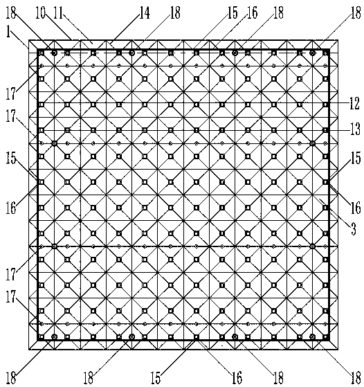
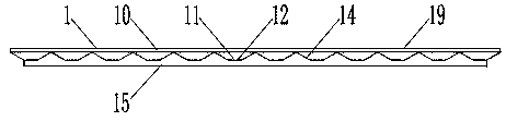
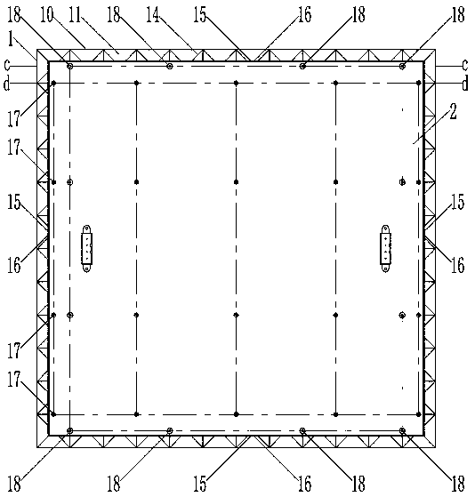
[0027] The description of the front side, the back side, and the surroundings in a light-emitting module embodiment of the present invention is based on the attached figure 1 based on the view direction.

[0028] An embodiment of a light-emitting module of the present invention, such as Figure 1 to Figure 5 As shown, it is characterized in that: the light-emitting module includes: a plurality of frustums 11 uniformly distributed in an array on the rear side of the panel 10, protruding backwards, and the top surface 12 of the frustum of the frustum facing backwards, The lamp socket 13 located in the center of the frustum body 11 and the protective edge 15 that surrounds all the lamp sockets 13 and protrudes backward, and a circle located inside the prot...


PUM


Abstract

The invention relates to a luminous module. The luminous module comprises a light diffusion module and a lamp panel, wherein the light diffusion module is integrally composed of a panel, a plurality of frustum bodies, lamp holes, protective edges and frustum stairs, the multiple frustum bodies are evenly and fully distributed on the rear side of the panel according to an array and protrude backwards, the top faces of the frustum bodies face backwards, the lamp holes are formed in the center parts of the frustum bodies, the protective edges surround all the lamp holes and protrude backwards, each circle of frustum stair is located on the inner side of the corresponding protective edge and is flushed with the top face of the corresponding frustum body, and the lamp panel is mounted within the range of the protective edges; light sources which are arrayed the same as the lamp holes are arranged on the lamp panel; and the lamp panel is fixedly mounted within the range of the protective edges, and thus the light sources are placed in the lamp holes. From the technical features, it can be seen that the multiple frustum bodies on the rear side face of the panel are of an integrated structure which is arrayed according to the array and evenly and fully distributed, any part for shielding light does not exist in the periphery, and thus shadowless splicing can be achieved; and the luminous module is suitable for backlight sources of large display equipment, large lamp boxes and large-area lighting facilities.

Description

technical field [0001] The invention relates to the technical field of backlight sources, in particular to a light emitting module. Background technique [0002] The application of backlight is extremely extensive, not only for TFT-LCD (liquid crystal display), but also widely used in light boxes, lighting and other special display equipment. Among them, the application field of light boxes is the most extensive, which involves the construction field (such as: window , lighting roof, lighting wall, signboard, emergency light source, etc.), industrial fields (such as: film viewer, instrument panel, machine identification, production line process instructions, metering equipment, etc.), lighting field (such as: flat light source, Light source curtains, light source walls, ground light sources, etc.), civil fields (such as: photo frames, decorative paintings, dressing tables, etc.), commercial fields (such as: item array cabinets, guide signs, identification signs, etc.), medic...

Claims


Application Information

Patent Timeline
IPC IPC(8): G09F13/04G02F1/13357
CPCG02F1/133606G02F1/133608G09F13/0409
Inventor 罗言超姚淑英
Owner 湖南凯星电子科技有限公司
Why Eureka
Try Eureka