For seals between the stator and rotor of electric motors and hub motors

A technology for in-wheel motors and seals, applied in electrical components, electric components, electromechanical devices, etc., can solve the problems of shortening the service life of in-wheel motors, lack of stable sealing support, unreliable position of seals, etc., and achieves easy molding and standardization. Production, post-maintenance and maintenance are convenient, and the effect of reducing the failure rate

Active Publication Date: 2020-07-17
ZHEJIANG VIE SCI & TECH
View PDF1 Cites 0 Cited by
  • Summary
  • Abstract
  • Description
  • Claims
  • Application Information

AI Technical Summary

Problems solved by technology

[0004] It is a common form of sealing structure for hub motors, but during use, since there is no stable sealing support, the grease needs to be replaced and cleaned frequently
Moreover, the seal cannot be directly formed between the stator and the rotor, the seal is not reliable enough, and the position of the seal is not reliable, thus shortening the service life of the hub motor

Method used


Image

  • For seals between the stator and rotor of electric motors and hub motors
  • For seals between the stator and rotor of electric motors and hub motors
  • For seals between the stator and rotor of electric motors and hub motors

Examples


Embodiment 1

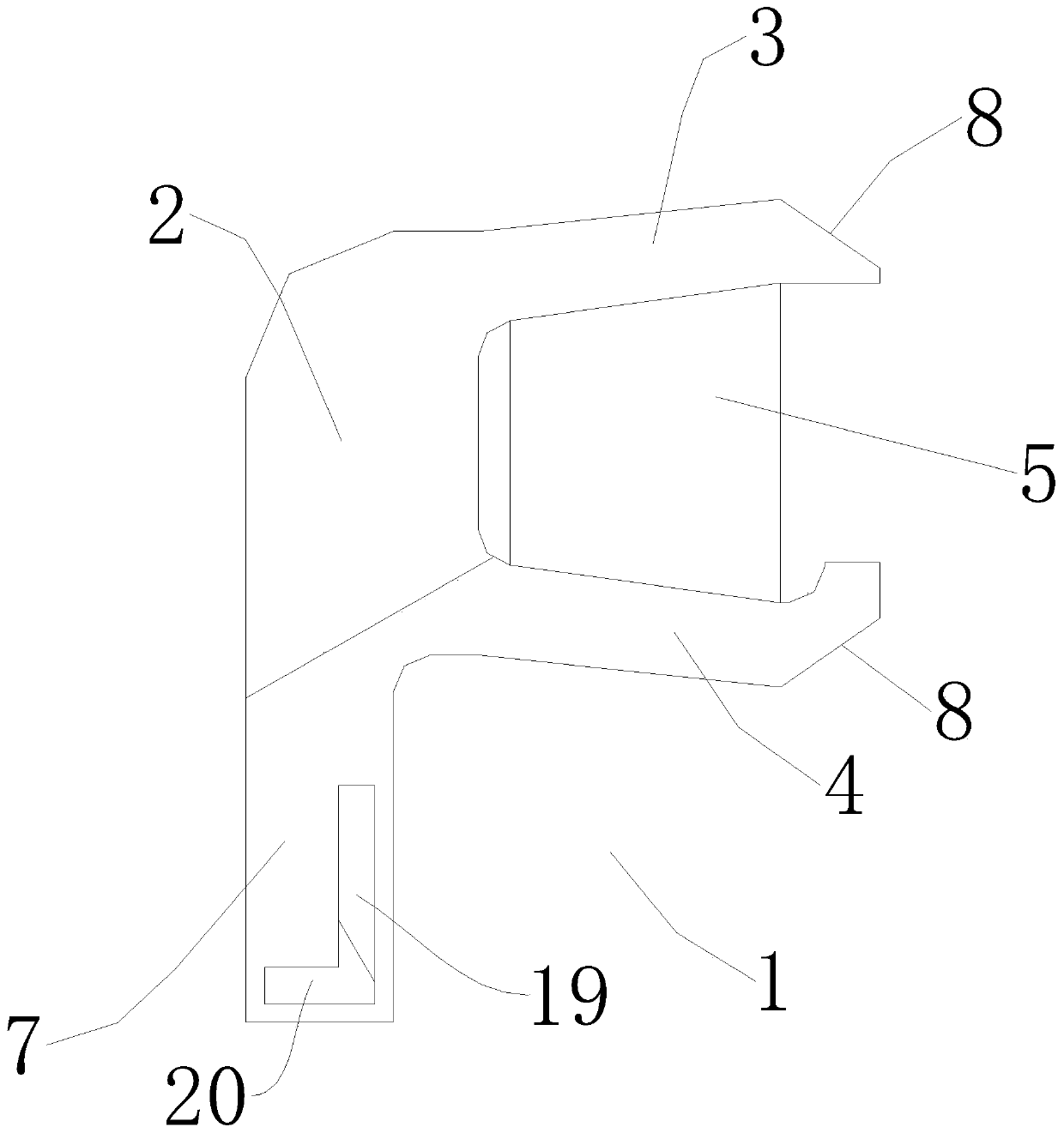
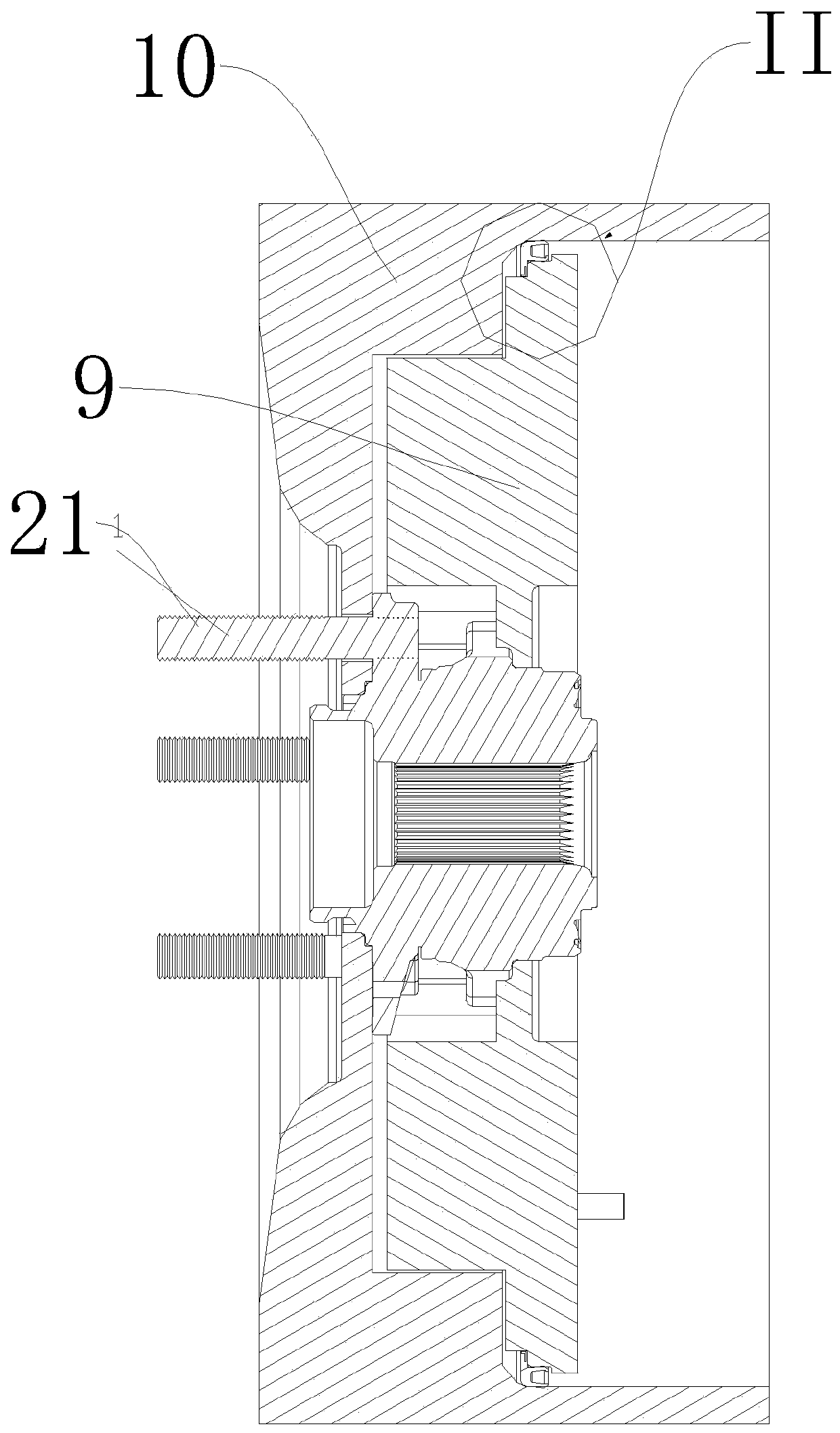
[0034] Such as figure 1 As shown, this embodiment provides a seal used between the stator and the rotor of the motor, which is applied to the hub motor in this embodiment. For ease of understanding, the installation of the in-wheel motor is first described. The rotating part of the bearing 21 of the in-wheel motor is installed with the wheel. The rotor 10 of the in-wheel motor is connected to the rotating part of the bearing 21 by bolts, so as to be fixed with the wheel. The rotor 10 It can drive the wheels to realize synchronous rotation. The stator 9 is connected with the non-rotating part of the bearing 21 through bolts and does not rotate. The coil of the stator 9 drives the rotor 10 to rotate, and the rotor 10 drives the wheels to rotate. This is the basic principle of the hub motor. Since there is a gap between the rotor 10 and the stator 9, external impurities will enter the interior of the hub motor and affect the hub motor. Therefore, this embodiment provides a seal 1...

Embodiment 2

[0040] Such as figure 1 , figure 2 and image 3 As shown, the present embodiment provides an in-wheel motor, including a rotor 10 and a stator 9. Since there is a gap between the rotor 10 and the stator 9, external impurities will enter the interior of the in-wheel motor and affect the in-wheel motor. Therefore, this The in-wheel motor of the embodiment also includes a seal 1 for isolating the inside of the in-wheel motor from the outside to achieve a sealing effect and to protect the internal parts of the motor from dust and water. Wherein the seal 1 adopts the seal 1 in the embodiment 1. The left side of the seal 1 is the outside of the hub motor, and the right side is the inside of the hub motor.

[0041] The specific installation structure is as follows, the rotor 10 is provided with an installation chamber 11, the stator 9 is arranged in the installation chamber 11, the first sealing lip 3 seals against the inner ring surface 12 of the installation chamber 11, and the...

Embodiment 3

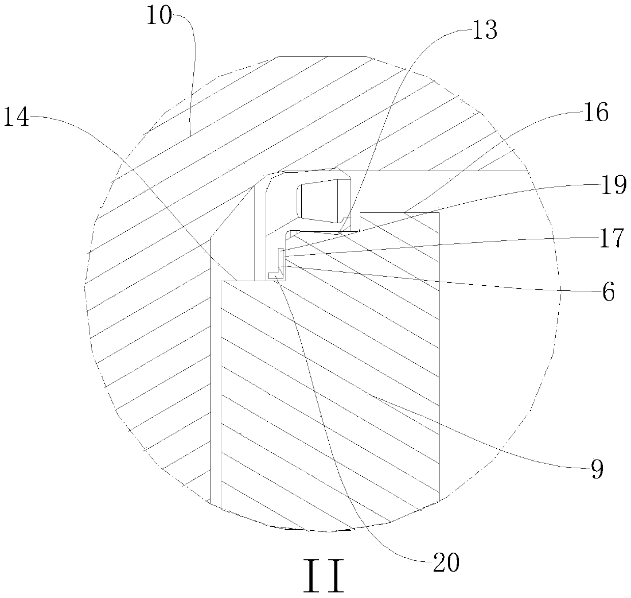
[0045] Such as figure 1 , figure 2 and Figure 4 As shown, this embodiment provides an in-wheel motor. The difference between this embodiment and Embodiment 2 is that it also includes a third outer ring surface 15 located on the left side of the second outer ring surface 14, and the third outer ring surface The diameter of 15 is smaller than the diameter of the second outer ring surface 14; the third outer ring surface 15 is arranged on the third outer ring surface 15 and a fixed ring 18 is installed, and the sealing ring 7 is inserted between the fixed ring 18 and the first transition end surface 17 In the formed space and sealed with the fixed ring 18 and the first transitional end surface 17, the sealing surface of the sealing ring 7 and the first transitional end surface 17 is the first sealing surface. The fixing ring 18 can ensure that the seal 1 is installed in the correct position on the shaft during installation, and at the same time ensure that the seal 1 is alway...


PUM


Abstract

The invention relates to the field of hub motor sealing and discloses a sealing member for use between the stator and the rotor of a motor and a hub motor. The sealing member (1) is used for line sealing, surface sealing, or multi-lip sealing a portion. The sealing member (1) comprises an annular support body (2). A first sealing lip (3) and a second sealing lip (4) are integrally formed on the support body (2). The first sealing lip (3), the second sealing lip (4) and the support body define a storage opening (5). The inside or outside of the support body (2), the inside or outside of the first sealing lip, or the inside or outside of the second sealing lip is provided with a metal skeleton (6) for improving the assembly strength of the sealing member (1). The sealing member can achieve reliable sealing and automatic compensation.

Description

technical field [0001] The invention relates to the field of hub motor seals, in particular to a seal used between a motor stator and a rotor and a hub motor. Background technique [0002] Chinese invention patent CN102007676B discloses an outer rotor type motor and an outer rotor type in-wheel motor. It discloses a technical solution as follows: the outer rotor type motor includes: a stator module formed in a cylindrical shape with a closed rear end, the stator The module is installed on the shaft passing through the central part of the rear end of the stator module; the stator is fixedly installed on the outer circumferential surface of the stator module; the main cooling part is arranged inside the stator module On the peripheral surface, in order to reduce the temperature of the corresponding part, the main cooling part includes one or more recessed grooves formed along the inner peripheral surface of the stator module, and the grooves are formed in a plurality of axial ...

Claims


Application Information

Patent Timeline
Patent Type & Authority Patents(China)
IPC IPC(8): H02K1/06
CPCH02K1/06H02K2201/03
Inventor 陈锋马志敏耿传亮黄梅仙齐晓刚
Owner ZHEJIANG VIE SCI & TECH
Why Eureka
Try Eureka