Movable positioner

A technology of positioner and limit hole, applied in the field of positioner, can solve the problems of increasing cost, occupying space, affecting work efficiency, etc., and achieving the effect of saving cost, improving efficiency, and convenient fixing operation.

Active Publication Date: 2019-08-27
瀚能机器人自动化(丹阳)有限公司
View PDF7 Cites 4 Cited by
  • Summary
  • Abstract
  • Description
  • Claims
  • Application Information

AI Technical Summary

Problems solved by technology

[0004] The purpose of the patent of the present invention is to provide a movable positioner, which has the advantages of convenient clamping and fixing operations, cost saving and improved efficiency, and solves the problem that the current traditional positioner can only be applied to processing panels of fixed size and type. It not only increases the cost of production and processing, but also takes up most of the space and affects work efficiency

Method used


Image

  • Movable positioner
  • Movable positioner
  • Movable positioner

Examples


Embodiment Construction

[0024] The technical solutions in the patent embodiments of the present invention will be clearly and completely described below in conjunction with the accompanying drawings in the patent embodiments of the present invention. Obviously, the described embodiments are only part of the embodiments of the patent of the present invention, not all implementations example. Based on the embodiments in the patent of the present invention, all other embodiments obtained by persons of ordinary skill in the art without making creative efforts belong to the protection scope of the patent of the present invention.

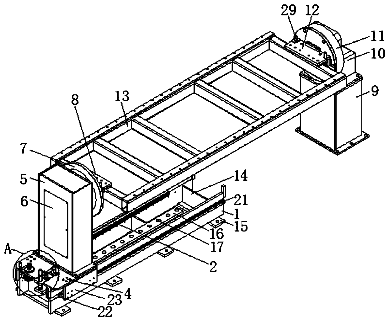
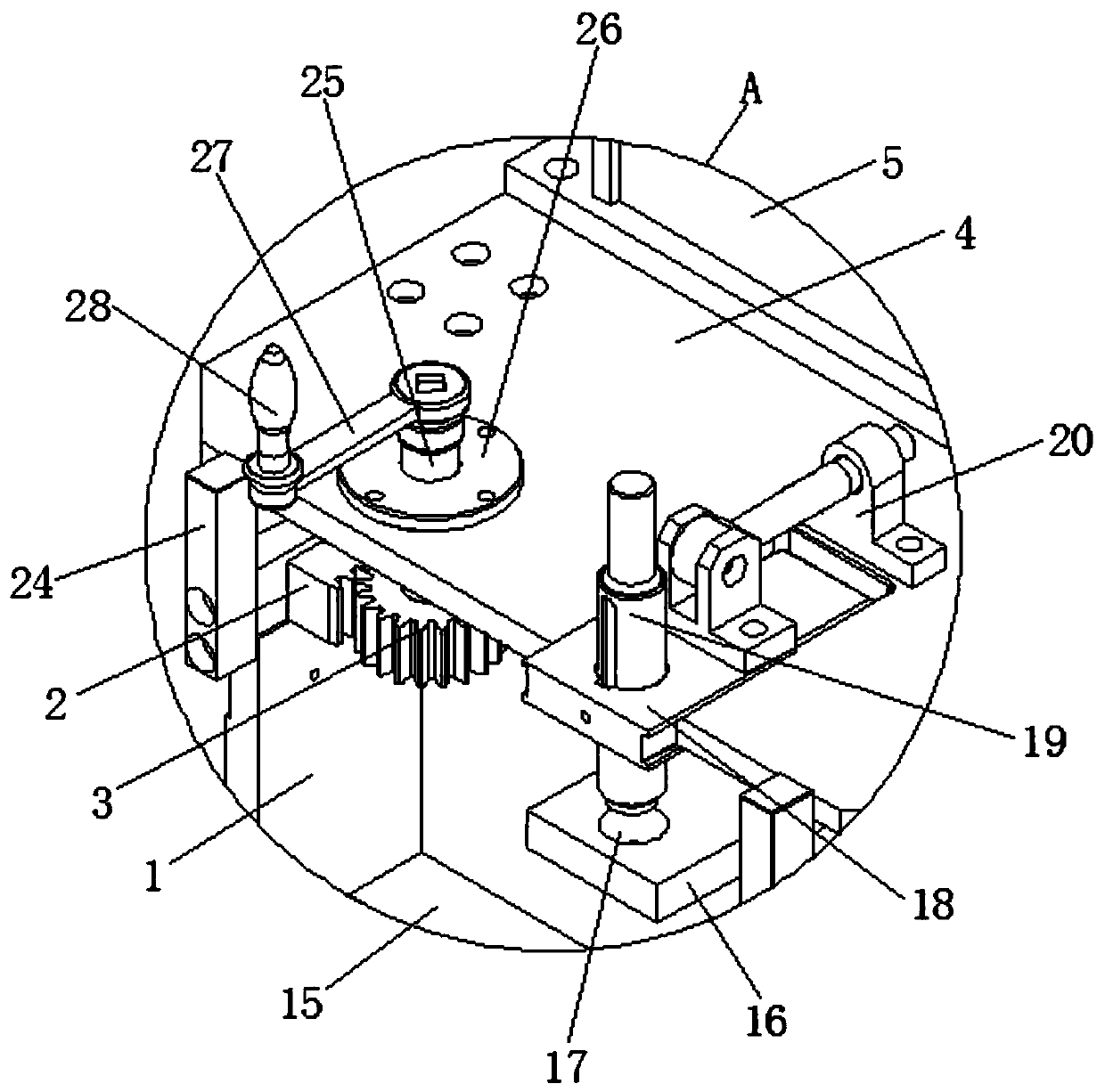
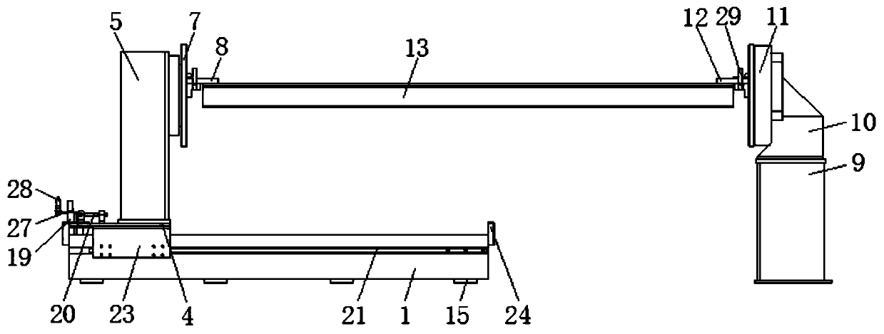
[0025] see Figure 1-5, a movable positioner, including a support plate 1 and a second box body 9, the inner wall of the support plate 1 is bolted with a rack plate 2, and the left side of the surface of the support plate 1 at the rear meshes with a gear plate 3. A fixed plate 4 is arranged above the support plate 1, and the top of the fixed plate 4 is bolted to the first box ...


PUM


Abstract

The invention discloses a movable positioner. The movable positioner comprises supporting plates and a second box. Rack plates are bolted on the inner walls of the supporting plates. The left side ofthe rack plate on the surface of the rear supporting plate is engaged with a gear plate. A fixing plate is arranged above the supporting plates. A box is bolted on the top of the fixing plate. An access door is arranged on the left side of the first box. According to the movable positioner, the supporting plates, the rack plates, the gear plate, the fixing plate, the first box, the access door, afirst rotary table, a first clamping piece, a second box, a fixing base, a second rotary table, a second clamping piece and a working frame are arranged, so that the positioner has the advantages of being convenient to clamp and fix, and capable of reducing the cost and improving the efficiency; the problems that an existing traditional positioner is only suitable for machining panels of fixed sizes and models, and consequentially, the production and machining cost is increased, a large space is occupied, and the working efficiency is affected are solved; and the movable positioner is worthy of popularization.

Description

technical field [0001] The patent of the present invention relates to the technical field of positioner, specifically a movable positioner. Background technique [0002] The positioner is a special welding auxiliary equipment, which is suitable for the welding displacement of the rotary work to obtain the ideal processing position and welding speed. It can be used together with the manipulator and welding machine to form an automatic welding center. It can also be used for manual work. The workpiece is displaced, and the rotation of the workbench adopts frequency converter stepless speed regulation with high speed regulation accuracy. The remote control box can realize remote operation of the workbench, and can also be connected with the manipulator and welding machine control system to realize linkage operation and welding displacement. The machine is generally composed of a worktable rotary mechanism and a turning mechanism. Through the lifting, turning and turning of the ...

Claims


Application Information

Patent Timeline
Patent Type & Authority Applications(China)
IPC IPC(8): B23K37/047
CPCB23K37/047Y02E10/50
Inventor 王严赵凯
Owner 瀚能机器人自动化(丹阳)有限公司
Why Eureka
Try Eureka