Injection mold
An injection mold and mold technology, applied in the field of injection molds, can solve the problem of inconvenient removal of injection molding products, and achieve the effects of novel design, convenient use, and convenient removal.
- Summary
- Abstract
- Description
- Claims
- Application Information
AI Technical Summary
Problems solved by technology
Method used
Image
Examples
Embodiment 1
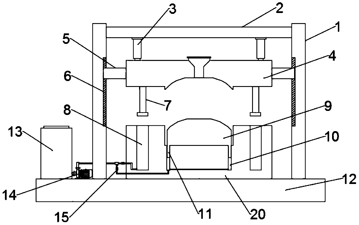
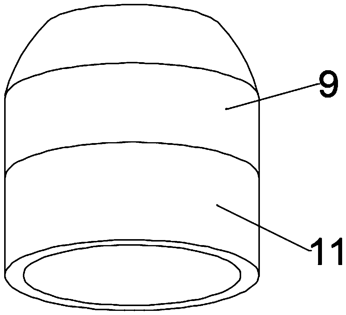
[0022] see figure 1 and 3 , in an embodiment of the present invention, an injection mold, an upper mold 4, a bottom plate 12 and a lower mold 20; the lower mold 20 is installed on the bottom plate 12, and the upper end of the bottom plate 12 is fixed with a crossbeam 2 through two symmetrically arranged brackets 1 , the upper mold 4 is driven by the driving assembly installed on the beam 2 to move up and down, the lower mold 20 is provided with a movable mold 9, and the movable mold 9 forms an injection flow channel with the upper mold 4 and the lower mold 20, so The lower end of the movable mold 9 is fixed with an annular block 11, and the annular block 11 is placed in the annular oil chamber 10 provided on the lower mold 20, and the annular oil chamber 10 communicates with the oil supply assembly. During the specific use process, the annular block 11 Placed in the annular oil chamber 10, the oil supply assembly absorbs the hydraulic oil in the annular oil chamber 10, so tha...
Embodiment 2
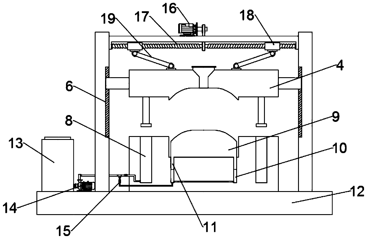
[0029] see figure 2 and 3 During the specific implementation process of the present invention, another embodiment is proposed to improve the present application. Specifically, the drive assembly includes a motor 16, a bidirectional threaded rod 17 and a threaded sleeve 18, and the bidirectional threaded rod 17 is arranged horizontally. And its two ends are respectively rotated and installed on the support 1, and the output shaft of the described motor 16 is connected with the described two-way threaded rod 17 by transmission belt, and two-way threaded rod 17 is symmetrically provided with two threaded sleeves 18, and the threaded sleeve 18 The lower end of the lower end is hinged with the upper end of the upper mold 4 through the connecting rod 19 hinged therewith. When the motor 16 drives the two-way threaded rod 17 to rotate, the upper mold 4 is driven to move vertically under the action of the threaded sleeve 18 and the connecting rod 19.
[0030] It should be noted that ...
PUM
 Abstract
Description
Claims
Application Information
 - R&D
- Intellectual Property
- Life Sciences
- Materials
- Tech Scout
- Unparalleled Data Quality
- Higher Quality Content
- 60% Fewer Hallucinations
Browse by: Latest US Patents, China's latest patents, Technical Efficacy Thesaurus, Application Domain, Technology Topic, Popular Technical Reports.
© 2025 PatSnap. All rights reserved.Legal|Privacy policy|Modern Slavery Act Transparency Statement|Sitemap|About US| Contact US: help@patsnap.com


