
Self-reset viscosity composite damper

A viscous damper and composite damping technology, applied in building types, buildings, building components, etc., can solve the high economic cost and time cost of repair, the difficulty of restoring the use function of the superstructure, and the self-resetting damper can not perform earthquake resistance. Fortification goals and other issues, to achieve the effect of saving economic and time costs, improving recoverability, and achieving maximum energy consumption

Active Publication Date: 2019-08-27
THE HONG KONG POLYTECHNIC UNIV
View PDF7 Cites 1 Cited by
  • Summary
  • Abstract
  • Description
  • Claims
  • Application Information

AI Technical Summary

Problems solved by technology

[0003] However, traditional dampers (such as metal dampers, friction dampers, and viscous dampers) tend to have insufficient reset ability after strong earthquakes, especially under the action of near-field pulse earthquakes. It is difficult to restore the function quickly, and the economic cost and time cost of repair are relatively high
[0004] Most of the existing self-resetting dampers are displacement-type dampers. Although they can show a flag-type hysteresis curve under the action of an earthquake, they can ensure that the main structure has a good self-resetting ability after an earthquake, but the flag-type The hysteresis curve also determines that the damper can only provide limited energy dissipation during a large earthquake, and often cannot effectively control the response of the main structure
At the same time, even if the displacement type damper can return to its original position after the earthquake, there are still residual stresses in the damper, which cannot be reused after the earthquake and often need to be replaced
If the structure can suffer aftershocks after the earthquake, the existing self-resetting damper will not be able to play the intended purpose of seismic fortification

Method used


Image

  • Self-reset viscosity composite damper
  • Self-reset viscosity composite damper
  • Self-reset viscosity composite damper

Examples


Embodiment Construction

[0032] The following will clearly and completely describe the technical solutions in the embodiments of the present invention with reference to the accompanying drawings in the embodiments of the present invention. Obviously, the described embodiments are only some, not all, embodiments of the present invention. Based on the embodiments of the present invention, all other embodiments obtained by persons of ordinary skill in the art without making creative efforts belong to the protection scope of the present invention.

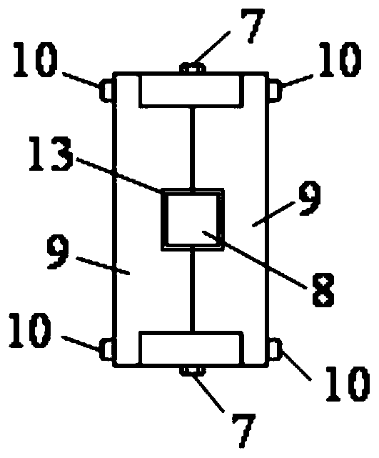
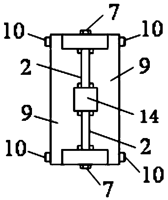
[0033] Please refer to Figure 1 to Figure 6 , figure 1 A schematic diagram of the front view structure of a self-resetting viscous composite damper provided for a specific embodiment of the present invention; figure 2 for figure 1 A sectional view taken along line A-A; image 3 yes figure 1 A sectional view taken along line B-B; Figure 4 yes figure 1 The front view of the bending restraint element in ; Figure 5 yes figure 1 Schematic diagram of the...


PUM


Abstract

The invention discloses a self-reset viscosity composite damper which comprises a viscosity damper, a guide rod, a U-shaped shape memory alloy element and a connecting frame. A cylinder body of the viscosity damper is fixedly connected with the connecting frame. One end of the guide rod penetrates the connecting frame and is connected with a piston rod of the viscosity damper. The branch end of the U-shaped shape memory alloy element is connected with the guide rod and the connecting frame. The shape memory alloy and the viscosity damper are used for forming the composite damper, characteristics of the self-reset damper can be developed in the initial stage of an earthquake, the characteristics of the viscosity damper are developed when the earthquake is strong, enough energy for consumption is provided, the characteristics of the self-reset damper is also developed before the earthquake is over, almost no residual deformation exists on the structure obtained after the earthquake, theearthquake resisting performance of the structure and the function recovery capability of the structure after the earthquake can be overall improved, and the self-reset viscosity composite damper hasa wide application prospect in the field of building structures and bridge engineering.

Description

technical field [0001] The invention relates to the technical field of energy dissipation and shock absorption of engineering structures, in particular to a self-resetting viscous composite damper. Background technique [0002] The energy-dissipating and shock-absorbing structure refers to the addition of energy-dissipating and shock-absorbing devices in the structure to form a new structural system with the original structure, and the additional energy-dissipating and shock-absorbing devices can significantly reduce the level of seismic action on the original structure, thereby achieving control of the structure. The purpose of earthquake response is to reduce the damage of the main structure. [0003] However, traditional dampers (such as metal dampers, friction dampers, and viscous dampers) tend to have insufficient reset ability after strong earthquakes, especially under the action of near-field pulse earthquakes. It is difficult to restore the function quickly, and the...

Claims


Application Information

Patent Timeline
IPC IPC(8): E04H9/02E04B1/98
CPCE04H9/021E04H9/0235
Inventor 王斌朱松晔
Owner THE HONG KONG POLYTECHNIC UNIV
Learn More