Power failure detection system
A technology for detecting system and power faults, applied in closed-circuit television systems, measuring devices, electrical components, etc., can solve problems such as broken wires, lack of devices and systems for handling hidden troubles, collapse of electric towers, etc., and achieves easy implementation and rich functions , good flexibility
- Summary
- Abstract
- Description
- Claims
- Application Information
AI Technical Summary
Problems solved by technology
Method used
Image
Examples
Embodiment 1
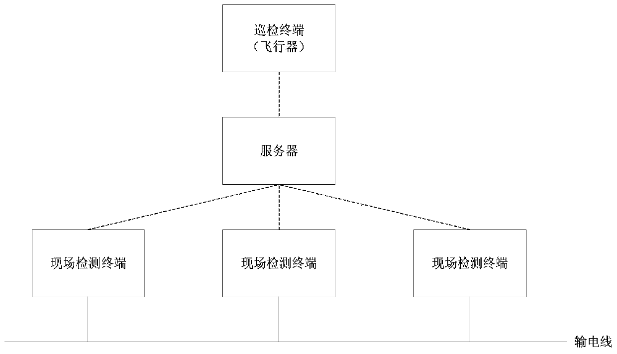
[0058] Such as Figure 1-12 , the power fault detection system has a power quality detection system, including a server, inspection terminals and multiple on-site monitoring terminals;
[0059] The on-site monitoring terminal is fixed at each detection point of the transmission line or substation to detect the voltage and current of the monitoring point; the on-site monitoring terminal transmits the sampled current and voltage information to the server;
[0060] There is a data analysis module in the server, which is used to analyze the power quality of the circuit. The power quality includes determining whether the voltage, current and each harmonic (also known as the distortion rate) exceed the preset value;
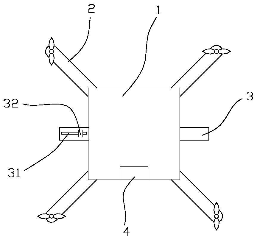
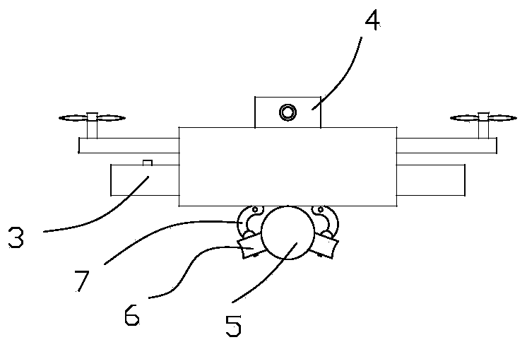
[0061] The inspection terminal includes an aircraft, and a camera 4 is arranged on the aircraft; the images and videos collected by the aircraft are sent to the server. The aircraft is used to check whether there is any loosening of the monitoring point or equipment d...
Embodiment 2
[0073] Embodiment 2: A power monitoring method for a substation corresponding to a power fault detection system
[0074] A method for monitoring electric energy in a substation, comprising the following steps:
[0075] Step 1: Data Acquisition
[0076] On-site monitoring terminals set up at each detection point of the substation collect power data;
[0077] The power data includes the instantaneous voltage and current amplitudes collected by voltage transformers and current transformers; the power data can further include the switch state data of each power switch, preferably, detected by sensors, such as detected by angle sensors Whether the switch is in action, or use the camera to take pictures to confirm whether the switch is in action;
[0078] Step 2: Data transfer
[0079] The on-site monitoring terminal transmits the collected power data to the server;
[0080] Step 3: Data Processing and Monitoring
[0081] The server processes the power data and analyzes the vol...
Embodiment 3
[0091] Embodiment 3: Power Fault Detection System
[0092] A power failure detection system, including a server and an ice-breaking robot arranged on a transmission line;
[0093] The ice-breaking robot is equipped with a camera and a remote control signal receiving module; the ice-breaking robot is also equipped with a wireless transmission module;
[0094] The image collected by the camera is uploaded to the server through the wireless transmission module; the server judges whether there is a fault or a potential fault based on the image. If the difference between the diameter of the transmission line and the original diameter exceeds the preset value, it means that there is ice on the transmission line. , there is a potential safety hazard, start deicing.
[0095] The front end of the ice-breaking robot is equipped with an encircling ice-breaking mechanism; the encircling ice-breaking mechanism is composed of two semi-circular components. When the two semi-circular compone...
PUM
 Abstract
Description
Claims
Application Information
 - R&D
- Intellectual Property
- Life Sciences
- Materials
- Tech Scout
- Unparalleled Data Quality
- Higher Quality Content
- 60% Fewer Hallucinations
Browse by: Latest US Patents, China's latest patents, Technical Efficacy Thesaurus, Application Domain, Technology Topic, Popular Technical Reports.
© 2025 PatSnap. All rights reserved.Legal|Privacy policy|Modern Slavery Act Transparency Statement|Sitemap|About US| Contact US: help@patsnap.com


