Device parameter measurement method and system and terminal equipment
A measurement method and technology of device parameters, applied in the direction of measuring devices, measuring electrical variables, instruments, etc., can solve problems such as inaccurate measurement of device parameters, and achieve the effect of improving measurement accuracy
- Summary
- Abstract
- Description
- Claims
- Application Information
AI Technical Summary
Problems solved by technology
Method used
Image
Examples
Embodiment 1
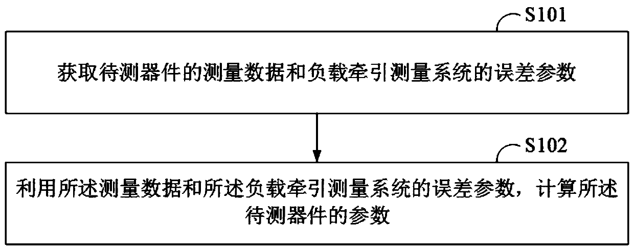
[0029] figure 1 It shows the implementation flow chart of the method for measuring device parameters provided by an embodiment of the present invention. For the convenience of description, only the parts related to the embodiment of the present invention are shown, and the details are as follows:
[0030] Such as figure 1 As shown, a method for measuring device parameters provided by an embodiment of the present invention includes:
[0031] S101, acquiring the measurement data of the device under test and the error parameters of the load-pull measurement system, the measurement data being the voltage wave measured by the internal receiver of the vector network analyzer in the load-pull measurement system based on the measurement of the device under test;
[0032] S102. Calculate parameters of the device under test by using the measurement data and error parameters of the load pull measurement system.
[0033] In this embodiment, the measurement data is the real-time voltage ...
Embodiment 2
[0104] Such as Image 6 As shown, the system provided by one embodiment of the present invention includes:
[0105] Vector network analyzer 1, source-end impedance adjuster 2, load-end impedance adjuster 3, source-end dual-directional coupler 4, load-end dual-directional coupler 5, and terminal equipment 21;
[0106] The first end of the source impedance adjuster 2 is used to connect the source signal source, the second end of the source impedance adjuster 2 is connected to the first end of the source dual directional coupler 4, the source The second end of the double-ended directional coupler 4 is connected to the first probe, and the first probe is used to connect the device under test 6;
[0107] The first end of the load end impedance adjuster 3 is used to connect the load end signal source, the second end of the load end impedance adjuster 3 is connected to the first end of the load end dual directional coupler 5, the load end The second end of the double-ended directio...
Embodiment 3
[0160] Figure 9 It is a schematic diagram of a terminal device provided by an embodiment of the present invention. Such as Figure 9 As shown, the terminal device 21 in this embodiment includes: a processor 910 , a memory 911 , and a computer program 912 stored in the memory 911 and operable on the processor 910 . When the processor 910 executes the computer program 912, it realizes the steps in each embodiment as described in Embodiment 1, for example figure 1 Steps S101 to S102 are shown. Alternatively, when the processor 910 executes the computer program 912, it realizes the functions of the terminal device in each system embodiment as described in Embodiment 2, for example Figure 7 The functions of modules 2100 to 2200 are shown.
[0161] The terminal device 21 refers to a terminal with data processing capabilities, including but not limited to computers, workstations, servers, and even smart phones with excellent performance, palmtop computers, tablet computers, per...
PUM
 Abstract
Description
Claims
Application Information
 - R&D
- Intellectual Property
- Life Sciences
- Materials
- Tech Scout
- Unparalleled Data Quality
- Higher Quality Content
- 60% Fewer Hallucinations
Browse by: Latest US Patents, China's latest patents, Technical Efficacy Thesaurus, Application Domain, Technology Topic, Popular Technical Reports.
© 2025 PatSnap. All rights reserved.Legal|Privacy policy|Modern Slavery Act Transparency Statement|Sitemap|About US| Contact US: help@patsnap.com


