Wiring terminal, fire alarm and wiring method

A technology of fire alarms and terminal blocks, which is applied in fire alarms, alarms, instruments, etc., can solve problems such as low connection reliability, insufficient locking force, and influence on conduction effect, so as to improve connection reliability and improve Wiring efficiency and the effect of saving wiring time

Pending Publication Date: 2019-08-27
深圳市高新投三江电子股份有限公司
View PDF0 Cites 2 Cited by
  • Summary
  • Abstract
  • Description
  • Claims
  • Application Information

AI Technical Summary

Problems solved by technology

[0003] Existing wiring terminals generally include a conductive voltage sheet, a locking sheet, and a screw passing through the conductive voltage sheet and the locking sheet. The conductive voltage sheet is fixedly connected with a conductive contact sheet. When connecting to an external cable, plug one end of the cable Insert between the conductive voltage piece and the locking piece, and then adjust the distance between the conductive voltage piece and the locking piece to make it smaller so as to fix the cable. However, the locking force provided by the existing terminal block is insufficient, and the wire When the cable is disturbed by the outside world, it will loosen, which will affect the conduction effect, and may even come out from between the conductive voltage piece and the locking piece, resulting in connection failure and low connection reliability.

Method used


Image

  • Wiring terminal, fire alarm and wiring method
  • Wiring terminal, fire alarm and wiring method
  • Wiring terminal, fire alarm and wiring method

Examples


Embodiment Construction

[0035] In order to make the purpose, technical solutions and advantages of the embodiments of the present invention clearer, a clear and complete description will be made below in conjunction with the technical solutions in the embodiments of the present invention. Obviously, the described embodiments are part of the embodiments of the present invention, and Not all examples. Based on the embodiments of the present invention, all other embodiments obtained by persons of ordinary skill in the art without making creative efforts belong to the protection scope of the present invention.

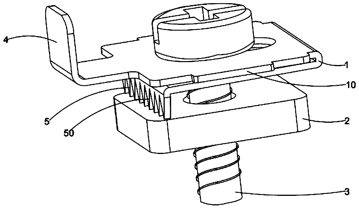
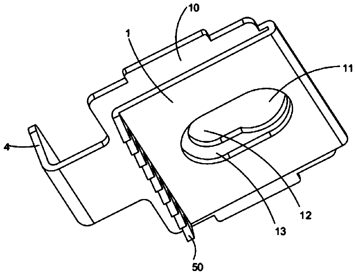
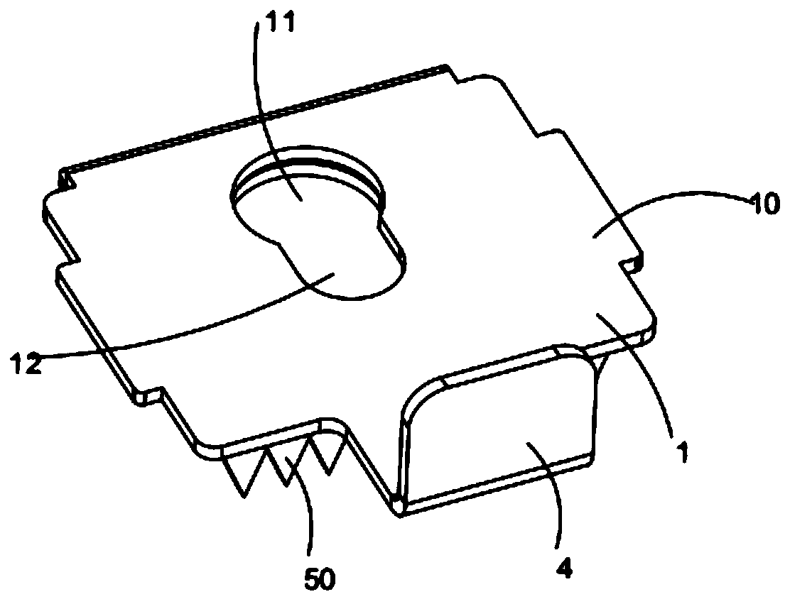
[0036] The schematic diagram of the structure of the terminal block of the preferred embodiment of the present invention is as follows: figure 1 shown, see also Figure 2 to Figure 6; Including conductive voltage sheet 1, locking sheet 2 and screw 3 for electrical connection with the outside world; conductive voltage sheet 1 is U-shaped or V-shaped; conductive voltage sheet 1 is bent from a meta...


PUM


Abstract

The invention relates to a wiring terminal. The wiring terminal comprises a conductive pressing piece, a locking piece and a screw; the conductive pressing piece is in a U or V shape; the conductive pressing piece is formed by bending a metal piece; the screw comprises a screw rod and a screw cap; the two side arms of the conductive pressing piece are provided with first through holes for allowingthe screw rod to penetrate through; the locking piece is provided with a threaded through hole matched with the screw rod; the screw cap is arranged on one side, away from the locking piece, of the conductive pressing piece; and the side arms, close to the locking piece, of the conductive pressing piece are fixedly provided with conductive puncture parts used for puncturing the insulating skin ofa cable. The conductive pressing piece is formed by bending the metal piece; a pre-tightening force can be generated in a process of clamping the cable; under the action of the pre-tightening force,the cable is not easy to loosen and is not easily separated from the conductive pressing piece and the locking piece; the wiring terminal has the functions of preventing the cable from being loosenedand separated, so that the connection reliability is improved; the conductive puncture parts are fixedly arranged on the conductive pressing piece; and the insulating skin of the cable is punctured byutilizing the conductive piercing parts, without being stripped in advance, so that the wiring efficiency is improved.

Description

technical field [0001] The invention relates to the technical field of wiring, more specifically, to a wiring terminal, a fire alarm and a wiring method. Background technique [0002] The fire alarm includes a fire alarm body and a base that are detachably connected to each other. The base is fixed with a terminal. The terminal has a conductive contact piece. The conductive contact piece is used to contact the conductive shrapnel of the fire alarm body. When installing, first Connect the external cables to the terminals, and then install the fire alarm body on the base. The electrical connection of the fire alarm body. [0003] Existing wiring terminals generally include a conductive voltage sheet, a locking sheet, and a screw passing through the conductive voltage sheet and the locking sheet. The conductive voltage sheet is fixedly connected with a conductive contact sheet. When connecting to an external cable, plug one end of the cable Insert between the conductive volta...

Claims


Application Information

Patent Timeline
Patent Type & Authority Applications(China)
IPC IPC(8): G08B17/00H01R4/2407H01R4/34F16B39/24
CPCF16B39/24G08B17/00H01R4/2407H01R4/34
Inventor 黄俊
Owner 深圳市高新投三江电子股份有限公司
Why Eureka
Try Eureka