Electric slip ring and fixing sleeve thereof

A fixed sleeve and electric slip ring technology, applied in the direction of circuits, current collectors, electrical components, etc., can solve the problems of large volume and uncompact structure, and achieve the effect of small volume, compact structure and simple structure

Active Publication Date: 2019-08-27
CHINA AVIATION OPTICAL-ELECTRICAL TECH CO LTD
View PDF6 Cites 2 Cited by
  • Summary
  • Abstract
  • Description
  • Claims
  • Application Information

AI Technical Summary

Problems solved by technology

[0004] The purpose of the present invention is to provide an electric slip ring to solve the problems of large volume and uncompact structure

Method used


Image

  • Electric slip ring and fixing sleeve thereof
  • Electric slip ring and fixing sleeve thereof
  • Electric slip ring and fixing sleeve thereof

Examples


Embodiment Construction

[0036] Embodiments of the present invention will be further described below in conjunction with the accompanying drawings.

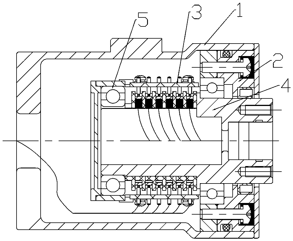
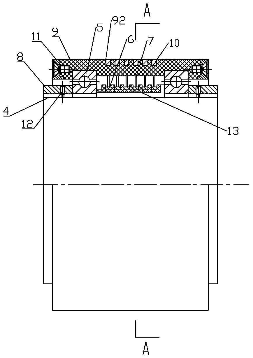
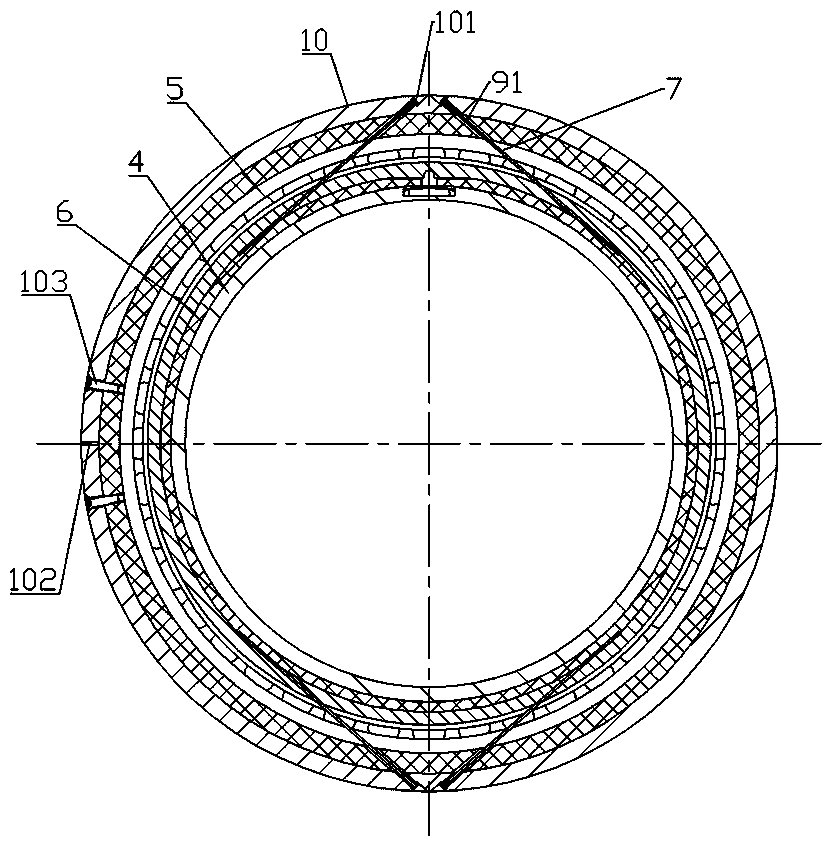
[0037] Embodiment 1 of the electric slip ring of the present invention, such as Figure 2 to Figure 3 As shown, the electric slip ring is applied in the field of connecting fixed parts and rotating parts. In this embodiment, the electric slip ring includes a rotating shaft 4, and the direction defining the rotating shaft 4 is along the front and rear directions. The rotating shaft 4 is sleeved with a plurality of insulating Sleeves 13, between two adjacent insulating sleeves 13, a conductive ring 6 sleeved outside the rotating shaft 4 is also clamped and fixed, and the two ends of the rotating shaft 4 are also sleeved with bearings 5, and the inner ring of the bearing 5 is fixed on the rotating shaft 4 Specifically, the insulating sleeve 13 is clamped on the rotating shaft 4 by the bearings 5 ​​on both sides. At the same time, a positioning piece is prov...


PUM


Abstract

The invention relates to an electric slip ring and a fixing sleeve thereof. The electric slip ring comprises a rotary shaft; a conductive ring is arranged on the rotary shaft; the electric slip ring further comprises the fixing sleeve arranged on the rotary shaft in a sleeving mode; the fixing sleeve comprises a fixing sleeve body; the fixing sleeve body is provided with an electric brush which isin contact with the conductive ring to realize circuit conduction; the fixing sleeve and the rotary shaft are oppositely supported through a bearing; the fixing sleeve body is formed by at least twoparts which mutually define a sleeve-shaped structure in the radial direction of the fixing sleeve; at least one end surface of the two axial ends of the fixing sleeve body is further provided with aconnecting structure used for connecting any two adjacent parts of the fixing sleeve body to connect the parts into a whole, so that the fixing sleeve is convenient to mount; and the fixing sleeve isdesigned to be of a thin-wall structure to further ensure relatively small radial wall thickness of the electric slip ring.

Description

technical field [0001] The invention relates to an electric slip ring and a fixed sleeve thereof. Background technique [0002] An electric slip ring is a device that transmits current and its signals. It transmits the current and its signals from a stationary part to another rotating part, in which a plurality of conductive rings are arranged at intervals on the rotating shaft to form the structure of the electric slip ring. The rotating part and the brush bundle are installed on the stationary part of the electric slip ring to form the stator part. The basic working principle is to realize the transmission of electrical signals through the sliding contact between the elastic brush in the conductive ring groove that can realize 360° rotation and the conductive ring. . [0003] The structure of a conventional electric slip ring is as follows figure 1 As shown in the figure, it is composed of a support member, a mounting plate part and a rotating shaft 4. The specific struc...

Claims


Application Information

Patent Timeline
IPC IPC(8): H01R39/08
CPCH01R39/08
Inventor 刘鹏飞
Owner CHINA AVIATION OPTICAL-ELECTRICAL TECH CO LTD
Why Eureka
Try Eureka