Solar frame and solar photovoltaic mounting assembly

A technology for installing components and solar energy, which is applied in the direction of solar thermal energy, solar thermal power generation, solar collectors, etc., can solve the problems affecting the quality of component product installation, complex solar frame processing technology, and wrong processing of installation holes, etc., to achieve convenient installation Fast, eliminate quality risks, and solve the effect of wrong and missed processing

Pending Publication Date: 2019-08-27
YONZ TECH CO LTD
View PDF0 Cites 0 Cited by
  • Summary
  • Abstract
  • Description
  • Claims
  • Application Information

AI Technical Summary

Problems solved by technology

In this way, the processing technology in the production process of the solar frame is complicated, the cost is high, and there are problems of wrong processing and missing processing of the stamped mounting holes, which affect the quality of the module product installation

Method used


Image

  • Solar frame and solar photovoltaic mounting assembly
  • Solar frame and solar photovoltaic mounting assembly
  • Solar frame and solar photovoltaic mounting assembly

Examples


Embodiment 1

[0041] Downswing 1:

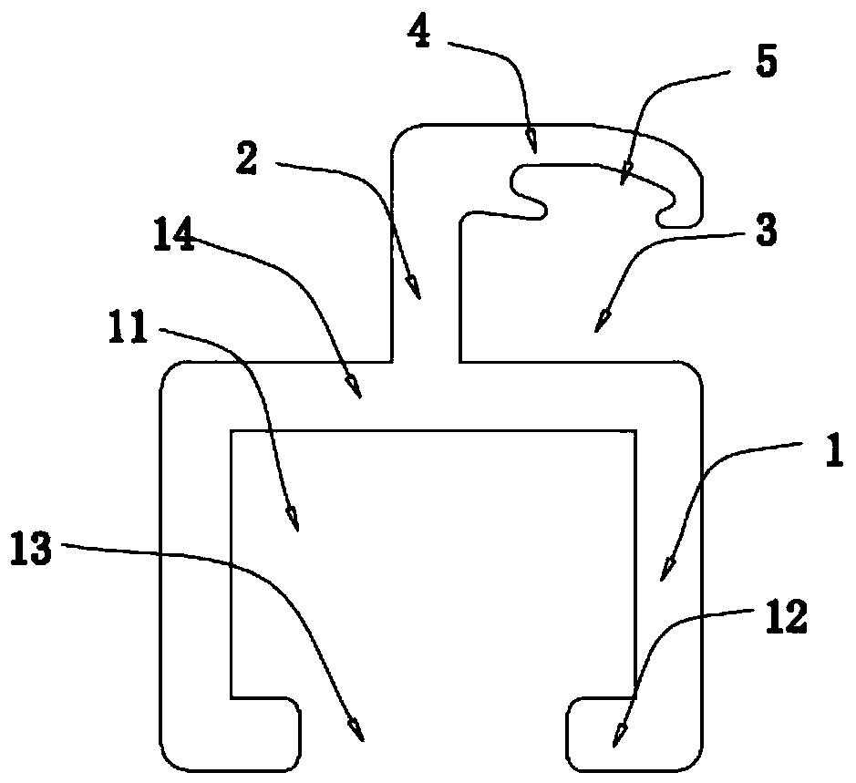
[0042] Such as figure 1 As shown, the lower rod 1 is an inverted "U"-shaped aluminum alloy rod, which can ensure good structural strength with a small weight. Down bar comprises left side, right side and top edge 14, and the inner side of down bar is cavity 11, is provided with a pair of support bar 12 in the bottom of down bar, and support bar is also aluminum alloy, and the length of support bar is equal to down bar length. The support bar is arranged in parallel with the lower bar, and the length of the support bar can also be slightly less than the length of the lower bar. Slightly less than this should be understood as the length difference between the lower bar and the support bar is 1-4cm. The support bar and the lower bar are integrally manufactured and formed, and the two support bars are respectively arranged at the bottom of the left side and the bottom of the right side, and a bayonet 13 is formed between the two support bars, and the bayone...

Embodiment 2

[0054] Downswing 1:

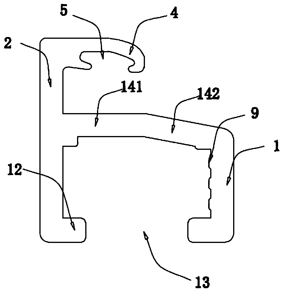
[0055] Such as figure 2As shown, the lower rod 1 is an inverted "U"-shaped aluminum alloy rod, which can ensure good structural strength with a small weight, and the lower rod is a sheet metal part. Down bar comprises left side, right side and top edge 14, and the inner side of down bar is cavity 11, is provided with a pair of support bar 12 in the bottom of down bar, and support bar is also aluminum alloy, and the length of support bar is equal to down bar length. The support bar is arranged in parallel with the lower bar, and the length of the support bar can also be slightly less than the length of the lower bar. Slightly less than this should be understood as the length difference between the lower bar and the support bar is 1-4cm. The support bar and the lower bar are integrally manufactured and formed, and the two support bars are respectively arranged at the bottom of the left side and the bottom of the right side, and a bayonet 13 is formed bet...

Embodiment 3

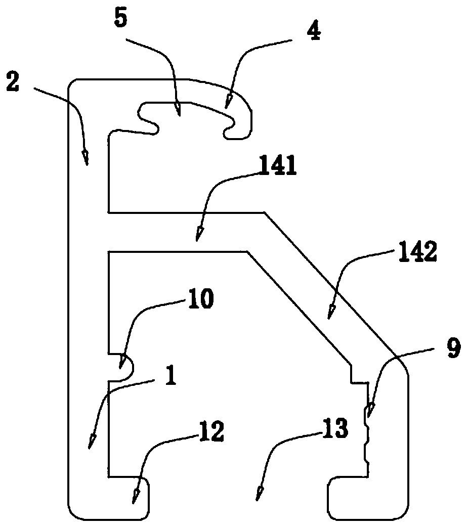
[0066] The difference between the third embodiment and the second embodiment is that the height of the left side of the lower rod is increased, and the inner wall of the left side of the lower rod is provided with a protrusion 10, and the protrusion is integrally formed with the lower rod. The function of the protrusion is to facilitate the positioning of the corner code.

[0067] Installation method one:

[0068] The same as the first installation method of Embodiment 2, the frame is arranged above the keel 8 and the lower surface of the frame is in contact with the keel, and the pressing block 6 is fixed and installed on the keel by bolts 7, and nuts 71 are set on the bolts accordingly to realize the keel and keel. The lock between the screws is fixed. The upper end of the briquetting block is a pressure head 62, which is in contact with the upper surface of the pressing plate; the lower end of the briquetting block is a pressure foot 63, which is in contact with the keel. ...


PUM


Abstract

Disclosed are a solar frame and a solar photovoltaic mounting assembly used for improving the universality of the solar photovoltaic mounting assembly. The solar frame comprises a lower rod, an upperrod and a pressing plate, wherein the lower rod comprises a left side edge, a right side edge and a top edge arranged between the upper part of the left side edge and the upper part of the right sideedge; a cavity is formed between the left side wall and the right side wall; supporting strips are arranged at the lower ends of the left side edge and the right side edge respectively; the upper rodis arranged above the lower rod and is fixedly connected with the lower rod; the pressing plate is fixedly connected with the upper portion of the upper rod; and a slot for clamping a solar panel is defined by the pressing plate, the upper rod and the lower rod. The solar photovoltaic mounting assembly comprises a frame, corner connecting components and a laminating part, wherein the frame refersto four rods on a rectangle; the corner connecting components are arranged between adjacent two frames and are used for connecting the two frames; and the laminating part is arranged above the frame and is provided with a plurality of wiring boxes. The solar frame and the solar photovoltaic mounting assembly disclosed by the invention have relatively high universality and are convenient to installand use.

Description

technical field [0001] The invention relates to the technical field of photovoltaic product installation, in particular to a solar frame and a solar photovoltaic installation assembly. Background technique [0002] At present, the installation of solar photovoltaic modules is basically to fix the C side of the module frame to the support keel by pressing blocks or bolts. When traditional solar modules are installed by bolts, punching holes must be punched on the C side of the solar frame to realize the connection with bolts and keels. In this way, the processing technology in the production process of the solar frame is complicated, the cost is high, and there are problems of wrong processing and missing processing of the stamped mounting holes, which affect the quality of module product installation. In addition, installation components are used in different products and environments, requiring the installation components to be universal. Contents of the invention [00...

Claims


Application Information

Patent Timeline
Patent Type & Authority Applications(China)
IPC IPC(8): H02S30/00F24S25/636
CPCF24S25/636H02S30/00Y02E10/47Y02E10/50
Inventor 汪献利王启张文启
Owner YONZ TECH CO LTD
Why Eureka
Try Eureka