Ka frequency band broadband receiving circuit

A broadband receiving and mixing circuit technology, applied in electrical components, transmission systems, etc., can solve the problems of general signal sensitivity, high power consumption, heavy weight, etc., and achieve the effect of reducing production costs and improving production efficiency

Inactive Publication Date: 2019-08-27
36TH RES INST OF CETC
View PDF2 Cites 4 Cited by
  • Summary
  • Abstract
  • Description
  • Claims
  • Application Information

AI Technical Summary

Problems solved by technology

[0003] However, the current Ka-band receiving circuits based on discrete components and component cascade technology generally have the defects of large size, heavy weight, and high power consumption, and the signal sensitivity is average.

Method used


Image

  • Ka frequency band broadband receiving circuit
  • Ka frequency band broadband receiving circuit
  • Ka frequency band broadband receiving circuit

Examples


Embodiment Construction

[0024] In order to make the object, technical solution and advantages of the present invention clearer, the implementation manner of the present invention will be further described in detail below in conjunction with the accompanying drawings.

[0025] In the description of this application, it should be noted that the terms "center", "upper", "lower", "left", "right", "vertical", "horizontal", "inner", "outer" etc. The indicated orientation or positional relationship is based on the orientation or positional relationship shown in the drawings, and is only for the convenience of describing the present application and simplifying the description, rather than indicating or implying that the referred device or element must have a specific orientation, use a specific orientation construction and operation, therefore should not be construed as limiting the application. In addition, the terms "first", "second", and "third" are used for descriptive purposes only, and should not be co...


PUM


Abstract

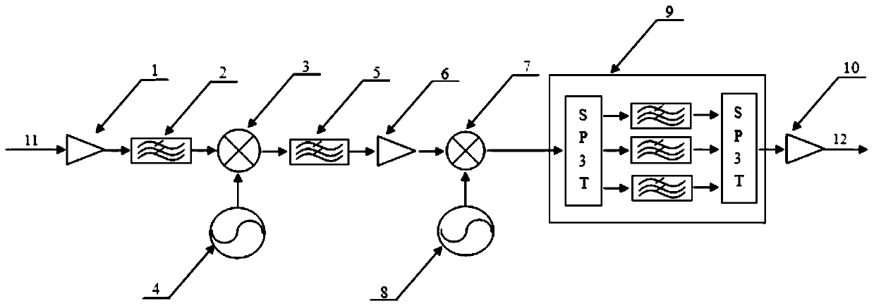
The invention discloses a Ka frequency band broadband receiving circuit which comprises a radio frequency amplifying circuit, a radio frequency filtering circuit, a frequency mixing circuit I, a localoscillator circuit I, an intermediate frequency filtering circuit I, an intermediate frequency amplifying circuit I, a frequency mixing circuit II, a local oscillator circuit II, an intermediate frequency switch filtering circuit II and an intermediate frequency amplifying circuit II. The radio frequency amplification circuit is sequentially connected with the radio frequency filter circuit, thefrequency mixing circuit I, the local oscillator circuit I, the intermediate frequency filtering circuit I, the frequency mixing circuit II, the local oscillator circuit II, the intermediate frequencyswitch filtering circuit II and the intermediate frequency amplifying circuit II in series. The frequency mixing circuit I is also connected with the local oscillator circuit I, and the frequency mixing circuit II is also connected with the local oscillator circuit II; wherein a chip used by each circuit is a chip-level device and is assembled by adopting a micro-assembly process. The chip-leveldevice is produced and assembled through the micro-assembly process, the size, the weight and the production cost are effectively reduced, the production efficiency is improved, and therefore the chip-level device can be widely applied to a communication system, a navigation system, a radar, a space electronic technology and other systems.

Description

technical field [0001] The invention relates to the field of microwave communication electronics technology, in particular to a Ka frequency band broadband receiving circuit. Background technique [0002] As the low-end spectrum resources are becoming increasingly exhausted with the rapid development of communication technology, and the demand for high-capacity communication technology is becoming increasingly urgent, in order to adapt to this development trend, microwave communication technology is showing a stronger development momentum. The Ka frequency band is part of the microwave frequency band of the electromagnetic spectrum. Its frequency range is 26.5-40GHz. This frequency band is directly higher than the K frequency band. It is usually used for satellite communications and has great development prospects. [0003] However, the current Ka-band receiving circuits based on discrete components and component cascade technology generally have the defects of large size, h...

Claims


Application Information

Patent Timeline
Patent Type & Authority Applications(China)
IPC IPC(8): H04B1/10H04B1/16
CPCH04B1/10H04B1/1638
Inventor 孟俊锋裴泽
Owner 36TH RES INST OF CETC
Why Eureka
Try Eureka