Blowback device for filter cartridges of dust remover

A technology of back-flushing device and dust collector, applied in the field of separation, can solve the problems of low dust removal rate, easy adsorption of dust on the surface of the filter cartridge, etc., and achieve the effects of commissioning airtightness, improving dust removal rate, and convenient control.

Pending Publication Date: 2019-08-30
安徽正义研磨环保科技有限公司
View PDF4 Cites 2 Cited by
  • Summary
  • Abstract
  • Description
  • Claims
  • Application Information

AI Technical Summary

Problems solved by technology

During the use of the dust collector, dust will adhere to the outer surface of the filter cartridge. In order to remove the dust adhered to the outer surface of the filter cartridge, people inject high-pressure air into the inner cavity of the filter cartridge to blow the air from the inside to the outside; Blowing technology has problems such as low dust removal rate and easy adsorption of dust on the surface of the filter cartridge.

Method used


Image

  • Blowback device for filter cartridges of dust remover
  • Blowback device for filter cartridges of dust remover
  • Blowback device for filter cartridges of dust remover

Examples


Embodiment 1

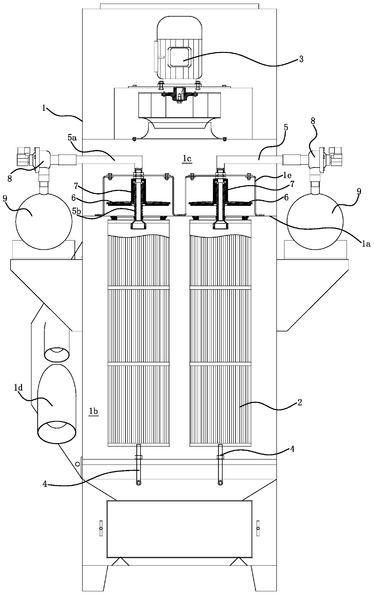
[0015] Embodiment 1: The dust collector includes a box body 1 and a filter cartridge 2. There is a horizontal partition 1a in the box body 1. The partition board 1a divides the inner cavity of the box body 1 into a dust removal chamber 1b and an air outlet chamber 1c. The air outlet chamber 1c is located at Above the dust chamber 1b. One or more air passage holes 1a1 are opened on the partition 1a, and the air passage holes 1a1 connect the dust removal chamber 1b with the air outlet chamber 1c. An air intake pipe 1d is installed on the side wall of the dust removal chamber 1b, and a fan 3 is installed on the top wall of the air outlet chamber 1c. When the fan 3 is running, the airflow enters the dust removal chamber 1b from the air inlet pipe 1d, enters the air outlet chamber 1c through the air hole 1a1, and finally passes through Fan 3 is discharged to the outside of casing 1.

[0016] The filter cartridge 2 is located in the dust removal chamber 1b of the box body 1. The fi...

Embodiment 2

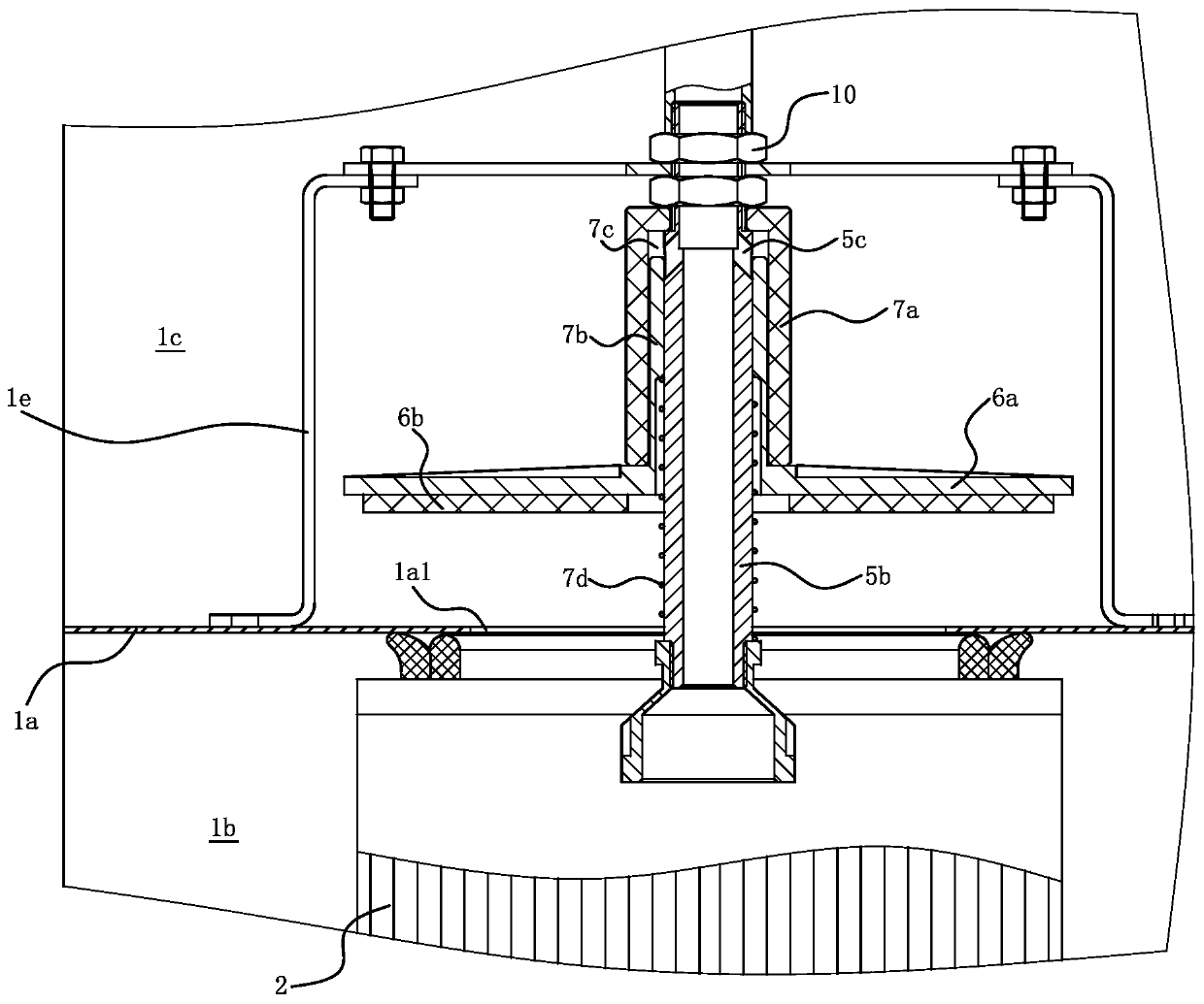
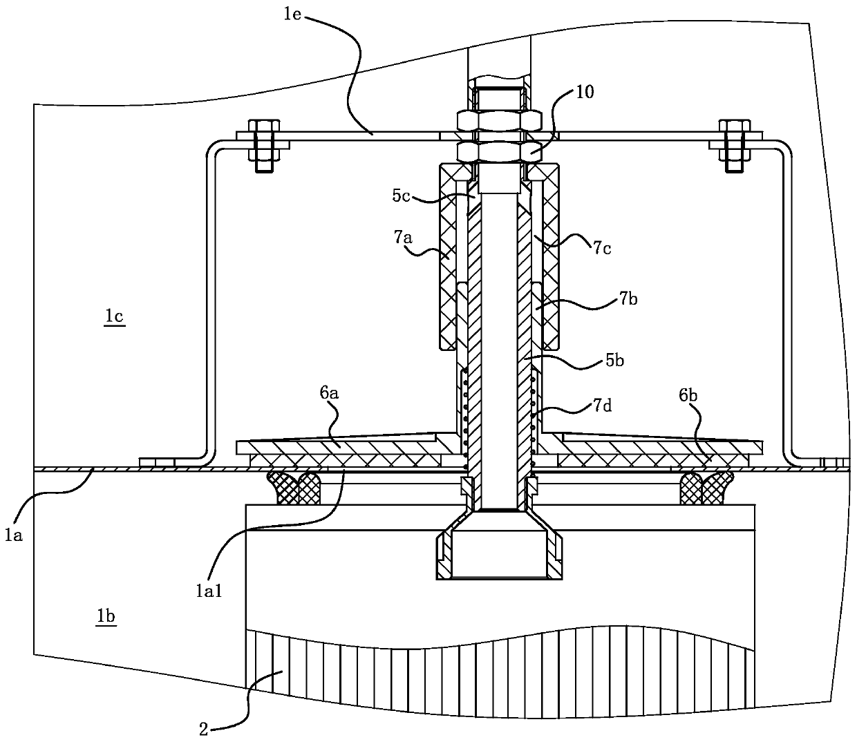
[0022] Embodiment 2: The structure and principle of this embodiment are basically the same as that of Embodiment 1. The basic similarities will not be described repeatedly, only the differences will be described. The difference lies in: the cover plate 6 and the pneumatic drive mechanism 7 are located in the box Below the partition plate 1a of the body 1, that is, the cover plate 6 and the pneumatic drive mechanism 7 are located inside the filter cartridge 2; the upper end of the piston 7b is fixedly connected with the cover plate 6. The spring 7d makes the piston 7b always move downward. When the injection of high-pressure gas into the air chamber 7c is stopped, the spring 7d drives the cover plate 6 to move downward, so that the cover plate 6 overcomes the airflow thrust generated by the fan 3, ensuring that the cover plate 6 Disengaged from the separator 1a and maintained in a state of being separated from the separator 1a.

Embodiment 3

[0023] Embodiment 3: The structure and principle of this embodiment are basically the same as that of Embodiment 1. The basic similarities are no longer redundantly described, and only the differences are described. The difference is that the pneumatic drive mechanism 7 is a cylinder, and one of the cylinders The air chamber 7c communicates with the blowback air pipe 5 , and a guide structure is formed between the cover plate 6 and the vertical section 5b of the back blow air pipe 5 .


PUM


Abstract

The invention provides a blowback device for filter cartridges of a dust remover, belongs to the technical field of separation, and solves the problem of insufficient type quantity of technical schemes for an existing blowback device for the filter cartridges of the dust remover. The blowback device for the filter cartridges of the dust remover comprises blowback air pipes fixed on a box body, theblowback air pipes pass through air passing holes and one ends are located in the inner cavity of the filter cartridges, and the other ends are located outside the box body; cover plates sleeve the blowback air pipes, pneumatic driving mechanisms with air chambers and pistons are installed on the box body, the pistons are connected with the cover plates, and the air chambers are communicated withthe blowback air pipes. When the blowback air pipes are filled with high-pressure air, the pistons of the pneumatic driving mechanisms drive the cover plates to move along the axial lines of the blowback air pipes in the direction near the air passing holes and can enable the cover plates to cover the air passing holes. The blowback device for the filter cartridges of the dust remover not only provides another technical scheme, but also has the advantages of simple structure and convenient operation, and is more beneficial for flexible arrangement of the filter cartridges.

Description

technical field [0001] The invention belongs to the technical field of separation, and relates to a dust collector, in particular to a blowback device for a filter cartridge of a dust collector. Background technique [0002] A dust collector is a device used to capture and separate dust particles suspended in the air. The types of dust produced by different working conditions are also slightly different, so people have proposed different types of dust collectors; among them, dust collectors with filter cartridges are especially suitable for working conditions with limited floor space and high filtration accuracy requirements. [0003] There are many related documents on dust collectors with filter cartridges, such as the dust collector proposed by the applicant (application publication number CN105289151A) and a dust collector (application publication number CN106422635A) and other technical solutions. During the use of the dust collector, dust will adhere to the outer surf...

Claims


Application Information

Patent Timeline
Patent Type & Authority Applications(China)
IPC IPC(8): B01D46/00B01D46/24
CPCB01D46/2411B01D46/58B01D46/71
Inventor 陈美青
Owner 安徽正义研磨环保科技有限公司
Why Eureka
Try Eureka