
A foam cutting machine

A cutting machine and foam technology, applied in metal processing and other directions, can solve the problems of low cutting accuracy and slow cutting efficiency, and achieve the effect of high-efficiency foam cutting ability

Active Publication Date: 2021-03-09
湖北世丰新材料有限公司
View PDF8 Cites 0 Cited by
  • Summary
  • Abstract
  • Description
  • Claims
  • Application Information

AI Technical Summary

Problems solved by technology

[0005] The object of the present invention is to provide a foam cutting machine to solve the problems of slow cutting efficiency and low cutting precision in the above-mentioned background technology

Method used


Image

  • A foam cutting machine
  • A foam cutting machine
  • A foam cutting machine

Examples


Embodiment Construction

[0027] It should be understood that the specific embodiments described here are only used to explain the present invention, not to limit the present invention.

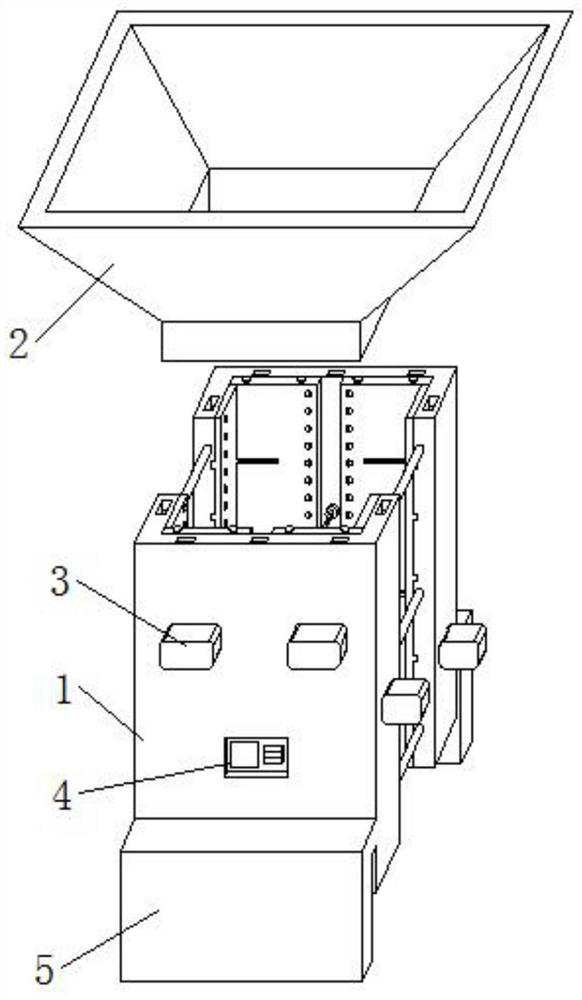
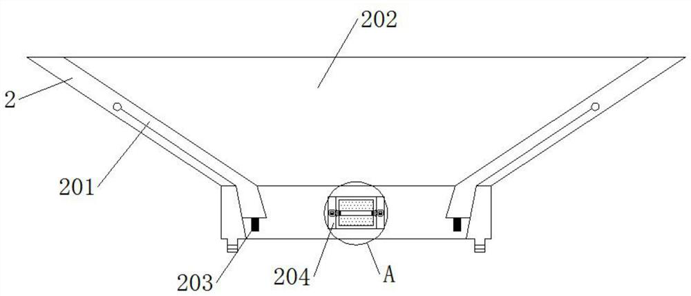
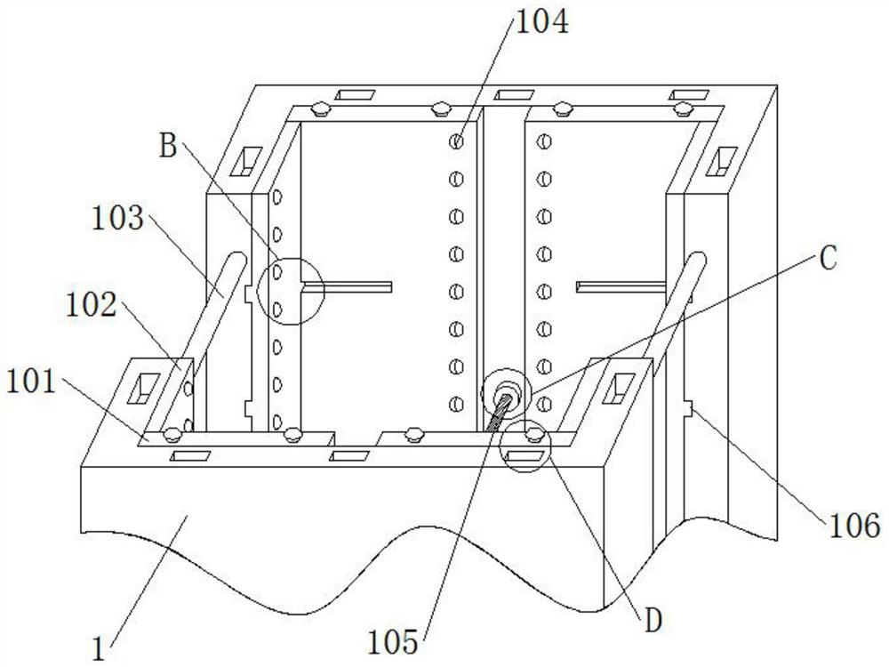
[0028] See attached figure 1 to attach Figure 8 , a foam cutting machine, including: a shell 1, a horizontal limit plate 101, an outer slide rail 1011, a connecting button 1012, a vertical limit plate 102, an anti-off slide plate 1021, a ball 1022, a connecting column 103, a guide plate bead 104, Electric heating wire 105, inner slide rail 106, socket groove 107, funnel 2, movable inner plate 201, top groove 202, elastic traction rope 203, correction wheel 204, small motor 2041, rotating shaft 2042, friction wheel body 2043, hydraulic pump 3. The controller 4 and the support plate 5, the top of the housing 1 is fixedly connected with the funnel 2 through the socket groove 107, the middle parts of the front and rear ends of the housing 1 are fixedly connected with the hydraulic pump 3, and the middle part of the fron...


PUM


Abstract

The invention provides a foam cutting machine. The foam cutting machine comprises a shell, a funnel, a hydraulic pump and a controller, wherein the top end of the shell is fixedly connected with a funnel through a sleeving groove, and hydraulic pumps are separately fixedly connected to the middle parts of the front end and the rear end of the shell; the controller is embedded in the middle of thefront end of the shell; supporting plates are integrally arranged at the bottoms of the front end and the rear end of the shell; and a movable inner plate is integrally arranged on the inner wall of the funnel; an elastic traction rope is fixedly connected to the bottom end of the movable inner plate; a top groove is embedded in the middle of the top end of the funnel; correcting wheels are fixedly connected to the front side and the rear side of the bottom end of the inner wall of the funnel; small motors are embedded in the middles of the left end and the right end of the funnel respectively; a rotating shaft is movably connected to the middle of the inner wall of the correcting wheels; a friction wheel body is fixedly connected to the outer wall of the rotating shaft; transverse limiting plates are movably connected to the front end and the rear end of the inner wall of the outer shell separately; and a connecting button is connected to the top end of each transverse limiting platein a threaded mode. The whole device is stable in structure and convenient to use and operate; the cutting efficiency of a foam plate is high; the cutting precision is high; and the time and labor aresaved during cutting.

Description

technical field [0001] The invention belongs to the technical field of foam cutting equipment, in particular to a foam cutting machine. Background technique [0002] Polystyrene foam board - also known as foam board, EPS board is made of expandable polystyrene beads containing volatile liquid foaming agent. The structural characteristics of closed cells are mainly used for building walls, roof insulation, composite panel insulation, cold storage, air conditioning, vehicle, ship insulation, floor heating, decoration and sculpture, etc. Foam materials are furniture packaging auxiliary materials, The demand is huge, the foam is used in different sizes, and the foam needs to be cut. [0003] The existing foam boards are usually cut manually, and the cutting personnel hold one or more foam boards to cut. The cutting efficiency is slow, the cutting accuracy is low, and the demand for the existing foam boards cannot be supplied. The way to increase production is to hire a lot of ...

Claims


Application Information

Patent Timeline
Patent Type & Authority Patents(China)
IPC IPC(8): B26F3/12B26D7/06B26D7/01
CPCB26D7/01B26D7/0641B26F3/12
Inventor 王华
Owner 湖北世丰新材料有限公司
Learn More