
Spacecraft Recovery Linear Electromagnetic Damping Device

A linear electromagnetic and damping device technology, which is applied to the landing device of the spacecraft, the system of the spacecraft returning to the earth's atmosphere, and the magnetic spring, can solve the problems of heavy weight, large diameter of the umbrella surface, and occupation of spacecraft load resources. Achieve large damping force and facilitate engineering application

Active Publication Date: 2022-01-18
HARBIN INST OF TECH
View PDF0 Cites 0 Cited by
  • Summary
  • Abstract
  • Description
  • Claims
  • Application Information

AI Technical Summary

Problems solved by technology

[0004] The purpose of the present invention is to solve the problem that the most commonly used spacecraft recovery device is a parachute landing system, but it has the disadvantages of large diameter of the umbrella surface, heavy weight, etc., and the problem of occupying the load resources of the spacecraft

Method used


Image

  • Spacecraft Recovery Linear Electromagnetic Damping Device
  • Spacecraft Recovery Linear Electromagnetic Damping Device
  • Spacecraft Recovery Linear Electromagnetic Damping Device

Examples


Embodiment 1

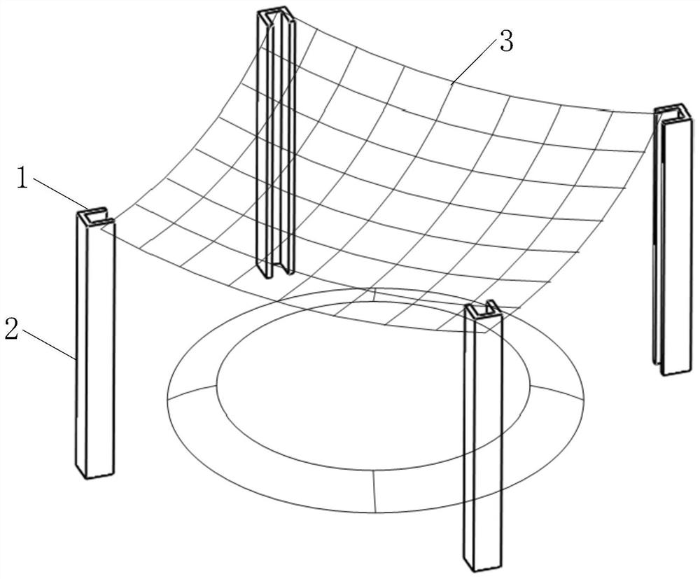
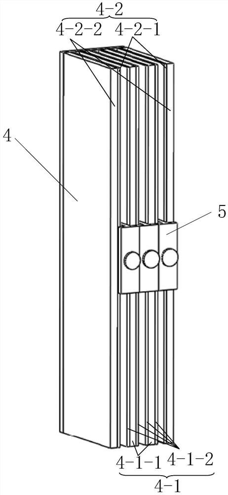
[0050] figure 1 A schematic diagram of the overall structure of Example 1 is shown. figure 2 A schematic diagram of the three-dimensional structure of the linear electromagnetic damper in Example 1 is shown. image 3 A schematic perspective view of the three-dimensional structure in which the driving coil is arranged on the stator in Embodiment 1 is shown. Figure 4 A schematic diagram of the mover structure is shown. Figure 8 A front view of the linear electromagnetic damper in Example 1 is shown. Figure 9 Shown in Example 1 Figure 8 Partial enlarged view of A. Figure 10 A front view of setting the drive coil on the stator in Embodiment 1 is shown. Figure 11 Shown in Example 1 Figure 10 Partial enlarged view of B.

[0051] refer to Figure 8 and Figure 9 As shown, the spacecraft recovery linear electromagnetic damping device of this embodiment includes a plurality of support frames 2, a recovery net 3, a plurality of linear electromagnetic dampers 1, a dry driv...

Embodiment 2

[0064] figure 1 A schematic diagram of the overall structure of Example 2 is shown. Figure 5 A schematic diagram of the three-dimensional structure of the linear electromagnetic damper in Example 2 is shown. Figure 6 A schematic diagram of the three-dimensional structure of the mover in Example 2 is shown. Figure 7 It shows a three-dimensional structure diagram of setting the driving coil on the mover in the second embodiment. Figure 12 A front view of the linear electromagnetic damper in Embodiment 2 is shown. Figure 13 shows the example 2 in Figure 12 Partial enlarged view of C. Figure 14 A front view of setting the drive coil on the mover in Example 2 is shown. Figure 15 shows the example 2 in Figure 14 Partial enlarged view of D.

[0065] Refer to 12 and Figure 13 As shown, the spacecraft recovery linear electromagnetic damping device of this embodiment includes a plurality of support frames 2, a recovery net 3, a plurality of linear electromagnetic dampe...


PUM


Abstract

The utility model relates to a linear electromagnetic damping device for spacecraft recovery, relating to the field of spacecraft recovery. The purpose of the present invention is to solve the problem that the parachute landing system, which is widely used in the existing spacecraft recovery device, has the disadvantages of large diameter and heavy weight of the umbrella surface, and the problem of occupying the load resources of the spacecraft. When it is ready to be recycled, multiple evenly arranged support frames support the recovery net, and the net angles of the recovery net are respectively connected with the linear electromagnetic damper movers of the multiple support frames. When the spacecraft falls into the recovery net, it will pull the mover of the linear electromagnetic damper to move downward. At this time, the permanent magnet on the stator cuts the No. 3 conductor plate on the mover to generate a magnetic field, which will generate a braking force against falling into the recovery net. The descending speed of the inner spacecraft is buffered to control the descending speed of the spacecraft. After the recovery is completed, the drive coil integrated in the linear electromagnetic damping is used to lift the mover and the recovery net to prepare for the next spacecraft recovery. It is used to recover spacecraft.

Description

technical field [0001] The invention relates to a rectilinear electromagnetic damping device for spacecraft recovery, belonging to the field of spacecraft recovery. Background technique [0002] Spacecraft recovery technology is a technology for a spacecraft to break away from its original orbit and enter the earth's atmosphere and land safely on the ground. Recovering a spacecraft belongs to the final phase of the spacecraft return process, the landing phase. After the spacecraft is decelerated by a special deceleration device, it is called a soft landing at a certain speed. Without special deceleration, it is called a hard landing. The recovery device is an important means to achieve a soft landing. The reliable performance of the spacecraft recovery device It plays an important role in the safe landing of spacecraft. [0003] The recovery of the spacecraft can choose land landing or sea splashing, and there are land recovery systems and sea recovery systems accordingly....

Claims


Application Information

Patent Timeline
Patent Type & Authority Patents(China)
IPC IPC(8): F16F6/00B64G5/00B64G1/62
CPCF16F6/00B64G5/00B64G1/62
Inventor 张赫寇宝泉牛旭陈雯王梦瑶
Owner HARBIN INST OF TECH
Learn More