Improved radar signal time-frequency analysis method

A technology of time-frequency analysis and radar signal, applied in the direction of radio wave reflection/re-radiation, utilization of re-radiation, measurement devices, etc., can solve the problem of multi-component nonlinear signal parameter separation, single-component nonlinear signal parameter estimation accuracy low, Low estimation accuracy and other issues, to achieve high time-frequency resolution and time-frequency aggregation, and optimal suppression effect

Active Publication Date: 2019-08-30
六盘水三力达科技有限公司
View PDF8 Cites 6 Cited by
  • Summary
  • Abstract
  • Description
  • Claims
  • Application Information

AI Technical Summary

Problems solved by technology

[0005] In order to solve the problems existing in the prior art, the present invention provides an improved radar signal time-frequency analysis method, which solves the problem of low accuracy of parameter estimation for single-component nonlinear signals, parameter separation and The problem of low estimation accuracy

Method used


Image

  • Improved radar signal time-frequency analysis method
  • Improved radar signal time-frequency analysis method
  • Improved radar signal time-frequency analysis method

Examples


Embodiment 1

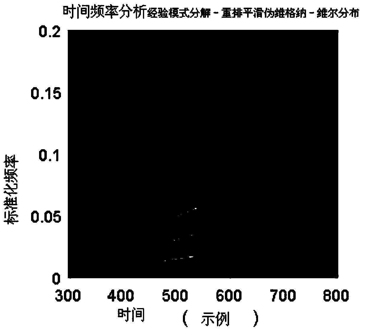
[0051] Below take three kinds of signals as example to illustrate the time-frequency analysis method of the present invention, embodiment one, simulation signal is the superposition of two sinusoidal signals and a linear signal, and signal analytical formula is:

[0052]

[0053] The number of signal sampling points is 2000, figure 2 In order to adopt the time-frequency analysis results based on the improved EMD algorithm and RSPWVD algorithm. Depend on figure 2 It can be seen that this method can describe nonlinear signals and linear signals very well, and for multi-component signals, the algorithm can not only analyze a single component of the signal but also analyze the multi-component signal as a whole.

Embodiment 2

[0054] In the second embodiment, the signals are the echo signals of three moving targets in the SAR scene. The observation mode of the SAR scene adopted in the second embodiment is strip type, and the target is observed in the way of front and side view, and the carrier frequency is set to 5.3 GHz , the shortest distance between the radar and the target is set to 20000m, the radar moving speed is set to 150m / s, the Doppler bandwidth is set to 80Hz, the sampling bandwidth is set to 200Hz, the initial positions of the three moving targets are set at the imaging center, and the three The speed direction of the moving target is the distance direction, and the speeds are 3m / s, 6m / s, and 9m / s respectively. First, the echo signal is compressed in the range direction, and then multiplied by the reference signal in the azimuth direction to eliminate the Doppler change caused by the radar movement. From the results of the previous step, the appropriate azimuth line is selected for time-...


PUM


Abstract

The invention discloses an improved radar signal time-frequency analysis method, which comprises the following steps: S1: performing signal decomposition operation based on an improved empirical modedecomposition algorithm on a signal to obtain a series of mutually orthogonal intrinsic mode function components and a residual component Res(t), wherein the t is signal duration; S2: screening the obtained intrinsic mode function components, and removing invalid intrinsic mode function components to obtain valid intrinsic mode function components; S3: performing Hilbert transformation on each obtained intrinsic mode function component to convert each basic mode component into an analytic signal; and S4: respectively performing time-frequency analysis based on a rearrangement smooth pseudo Wigner-Ville distribution algorithm on the valid intrinsic modal function components to obtain an analysis result after the time-frequency analysis processing of the rearrangement smooth pseudo Wigner-Ville distribution algorithm. The improved radar signal time-frequency analysis method of the invention solves the problems of low parameter estimation precision for single-component nonlinear signals and low parameter separation and estimation precision for multi-component nonlinear signals in the conventional method.

Description

technical field [0001] The invention relates to the field of time-domain analysis, in particular to an improved radar signal time-frequency analysis method. Background technique [0002] Nowadays, time-frequency technology has developed into a hot technology, among which signal analysis is an important field of time-frequency analysis technology application. Common time-frequency analysis algorithms include short-time Fourier transform, Wigner-Ville distribution (WVD), wavelet transform, Hilbert-Huang Transform (HHT) and more. Time-frequency analysis is to use a variety of mathematical transformations on digital signals to decompose and describe the local features of the signal from the perspective of time-frequency domain, so as to achieve anatomy and a more comprehensive understanding of the subtle features of the signal. [0003] As a two-dimensional signal analysis tool, time-frequency analysis is more and more widely used in the field of signal analysis. However, the ...

Claims


Application Information

Patent Timeline
Patent Type & Authority Applications(China)
IPC IPC(8): G01S7/41G01S13/90
CPCG01S7/41G01S13/9017G01S13/9029
Inventor 陈锟山潘方博鞠志远卢涵宇袁咏仪张旭
Owner 六盘水三力达科技有限公司
Why Eureka
Try Eureka