Microwave amplitude limiter
A limiter and microwave technology, which is applied in the field of limiters, can solve the problems of limiting the large-scale application of the waveguide plasma limiter in scientific experiments, and the inability to realize the on-line debugging of the limiter power, so as to achieve large-scale industrial production, Low air tightness requirements and low cost effect
- Summary
- Abstract
- Description
- Claims
- Application Information
AI Technical Summary
Problems solved by technology
Method used
Image

Examples
Embodiment 1
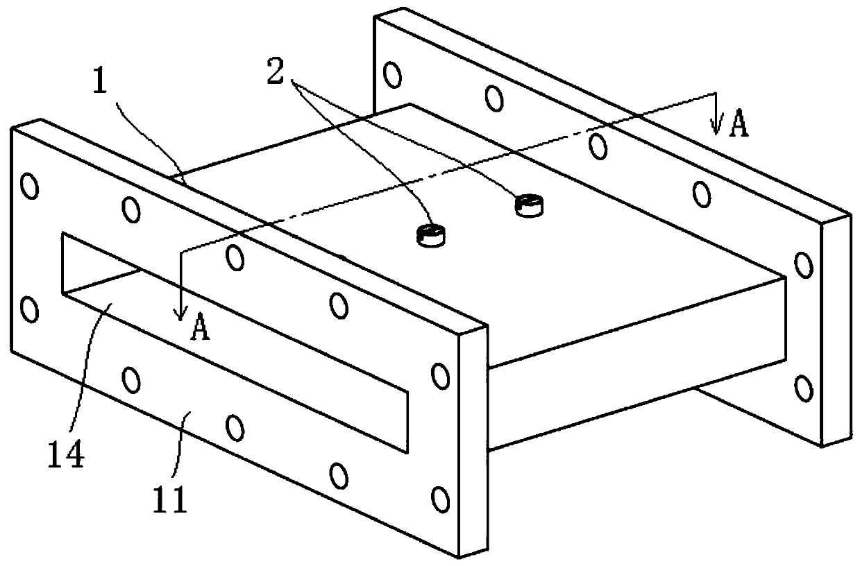
[0078] figure 1 An embodiment of a microwave limiter among numerous embodiments of the present invention is shown as an example. The microwave limiter includes a waveguide 1 and a first probe 2 .
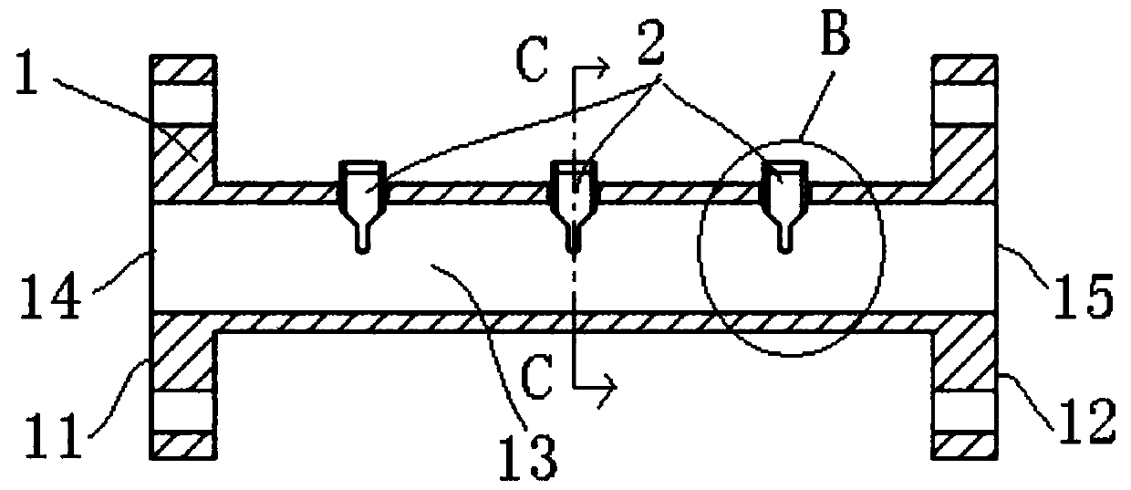
[0079] see also Figure 2-4 , the waveguide 1 is a rectangular waveguide, and its side walls include wide and narrow side walls. The shape of the waveguide 1 is rectangular, and flanges are arranged at both ends thereof. The waveguide 1 includes opposite end faces 11, 12, a waveguide cavity 13 and three first through holes. The waveguide cavity 13 runs through the two end faces 11, 12, and the waveguide cavity 13 is rectangular. The first opening 14 and the second opening 15 are respectively formed on the two ends 11 and 12 of the waveguide cavity 13 . Three first through holes are arranged on the wide side wall of the waveguide cavity 13 and arranged in a row along the longitudinal direction of the waveguide cavity 13 .
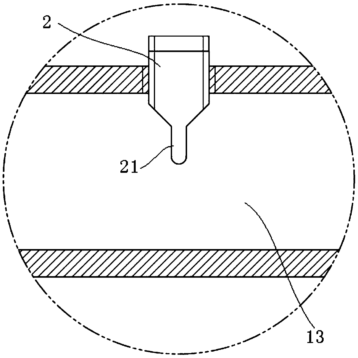
[0080] The number of the first probes 2 is three, and o...
Embodiment 2
[0087] see Figure 9-12 The difference between the microwave limiter shown in this embodiment and the microwave limiter shown in Embodiment 1 is that: three first through holes are arranged on the wide side wall of the waveguide cavity 13, and arranged in a row along the waveguide cavity 13 horizontally; Including 3 second through holes and 3 second probes 3, the 3 second through holes are set on the wide side wall of the waveguide cavity 13 opposite to the wide side wall where the first through hole is located and correspond to the first through holes one by one And concentric, one end of the second probe 3 has a second tip 31, a second probe 3 is installed in each second through hole and the second probe 3 can move back and forth axially along the second through hole, The second tip 31 protrudes into the waveguide cavity 13, and the first and second tips 21, 31 are arranged opposite to each other. Other than that, everything else is the same as the microwave limiter shown i...
Embodiment 3
[0094] see Figure 17-23The difference between the microwave limiter shown in this embodiment and the microwave limiter shown in Embodiment 2 is that the three first and second through holes are respectively arranged on the opposite wide side walls of the waveguide cavity 13, and respectively along the waveguide The cavity 13 is arranged in a row in the longitudinal direction, and the three second through holes are arranged in a row in the longitudinal direction along the waveguide cavity 13; the second through holes correspond to the first through holes and are concentric, and the first and second tips 21, 31 are arranged opposite to each other, which is beneficial to The microwave plasma is excited; it also includes the air hole 4, the first sealed resonant window 5 and the second sealed resonant window 6; the air hole 4 communicates with the waveguide cavity 13, which is used to fill the waveguide cavity with an inert gas or a mixed gas, and the inflation is completed After...
PUM
 Abstract
Description
Claims
Application Information
 - R&D
- Intellectual Property
- Life Sciences
- Materials
- Tech Scout
- Unparalleled Data Quality
- Higher Quality Content
- 60% Fewer Hallucinations
Browse by: Latest US Patents, China's latest patents, Technical Efficacy Thesaurus, Application Domain, Technology Topic, Popular Technical Reports.
© 2025 PatSnap. All rights reserved.Legal|Privacy policy|Modern Slavery Act Transparency Statement|Sitemap|About US| Contact US: help@patsnap.com