Slagging dedusting equipment for boiler in power plant

A technology for dust removal equipment and power plants, applied in the field of boilers, can solve problems such as inability to completely remove slag ash and low work efficiency, and achieve the effects of reducing non-processing time, improving work efficiency, and ensuring cleaning effects.

Inactive Publication Date: 2019-09-03
黄明佳
View PDF5 Cites 1 Cited by
  • Summary
  • Abstract
  • Description
  • Claims
  • Application Information

AI Technical Summary

Problems solved by technology

[0003] During the use of the boiler, a lot of slag will be generated on the inner wall, and the existing cleaning method is to wash with water manually. However, the working efficiency of this cleaning method is too low, and the slag on the inner wall cannot be completely removed, which is difficult to meet the requirements of modern industry. Production needs, so the present invention provides a boiler slag removal and dust removal equipment for power plants to solve the above problems

Method used


Image

  • Slagging dedusting equipment for boiler in power plant
  • Slagging dedusting equipment for boiler in power plant
  • Slagging dedusting equipment for boiler in power plant

Examples


Embodiment 1

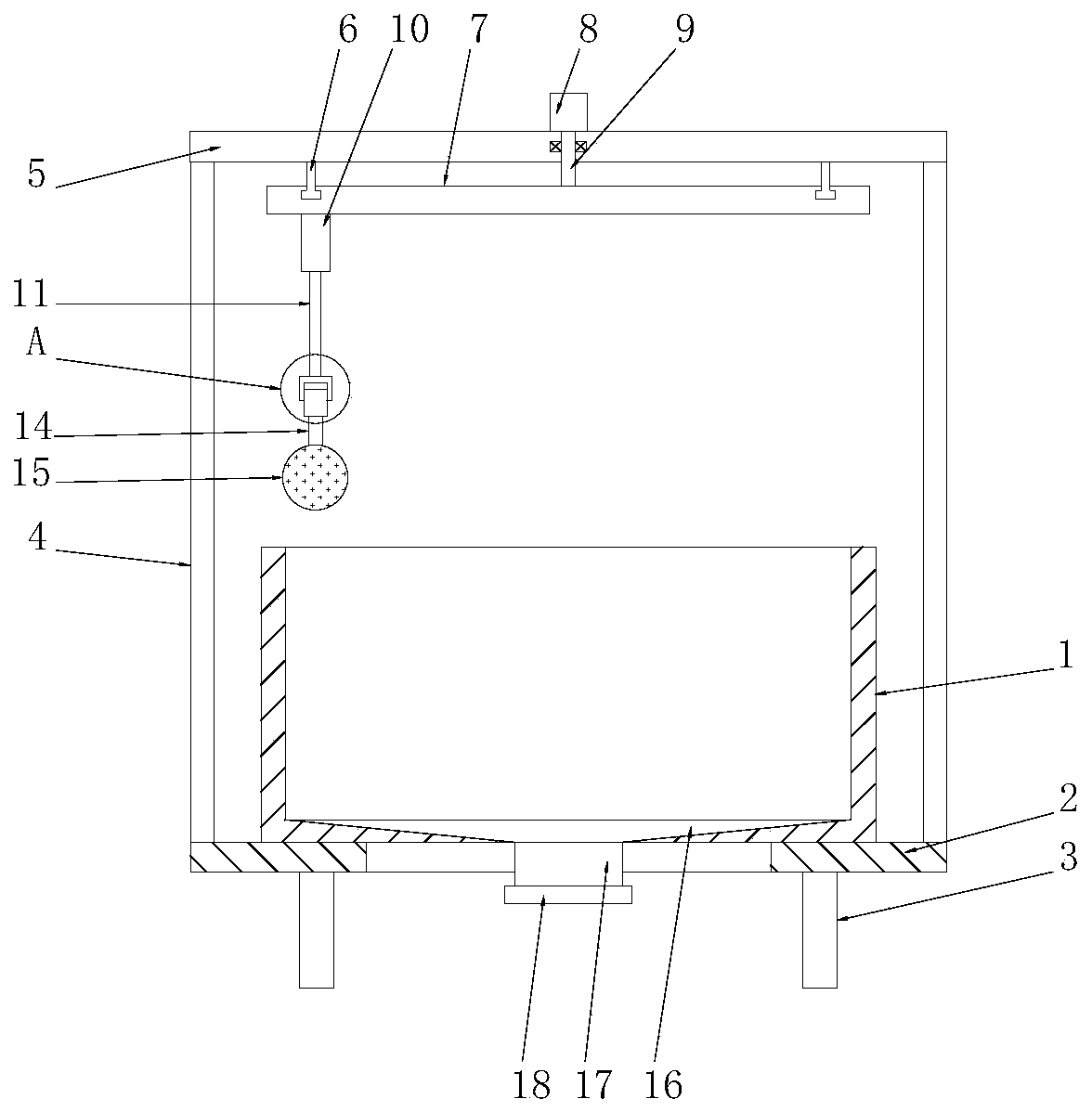
[0026] see Figure 1-3 , a boiler slag removal and dust removal equipment for a power plant, comprising a boiler body 1, a seat plate 2 is installed on the bottom end of the boiler body 1, the seat plate 2 is a ring structure, and the bottom end of the seat plate 2 is evenly installed with Several legs 3, the bottom end of the boiler body 1 is connected through the slag discharge pipe 17, the slag discharge pipe 17 is arranged in the inner cavity of the seat plate 2, the bottom end of the slag discharge pipe 17 is covered with a sealing cover 18, the boiler body The slag in the boiler body 1 is discharged through the slag discharge pipe 17, which is convenient for cleaning the slag in the boiler body 1.

[0027] The top of the seat plate 2 is evenly equipped with a number of uprights 4, and the tops of all the uprights 4 are jointly fixed with a top plate 5, and a feed mechanism is installed on the top plate 5, and a telescopic frame is installed on the feed mechanism. mechan...

Embodiment 2

[0030] This embodiment is a further elaboration on the basis of Embodiment 1. The feed mechanism includes a rotating motor 8, a slide rail 6 and a turntable 7. The rotating motor 8 is installed on the top of the top plate 5, and the slide rail 6 is installed At the bottom end of the top plate 5, the slide rail 6 is a ring structure, the rotating motor 8 is arranged on the axis of the slide rail 6, the turntable 7 is slidably connected to the slide rail 6, and the top of the turntable 7 is fixedly connected to the rotating shaft 9 The top of the rotating shaft 9 runs through the top plate 5 and is fixedly connected to the motor shaft of the rotating motor 8. The rotating shaft 9 and the top plate 7 are connected in rotation. The telescopic mechanism is installed on the bottom side of the turntable 7. 8 drives the rotating shaft 9 to rotate, and uses the rotating shaft 9 to drive the turntable 7 to rotate along the slide rail 6, thereby driving the telescoping mechanism to rotate...

Embodiment 3

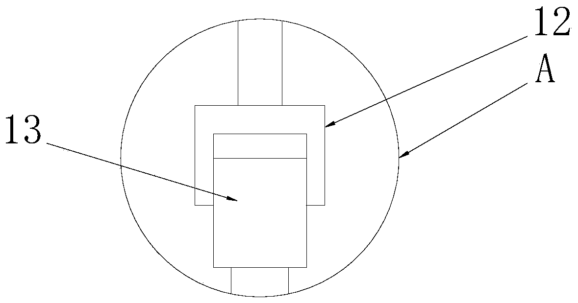
[0032]This embodiment is a further elaboration on the basis of Embodiment 1. The telescopic mechanism includes an electric telescopic rod 10, which is fixedly installed on the turntable 7, and the bottom end of the telescopic rod 11 on the electric telescopic rod 10 Fixed connection connecting frame 12, described connecting frame 12 is U-shaped structure, and cleaning motor 13 is installed in connecting frame 12, and the motor shaft of cleaning motor 13 is fixedly connected cleaning rod 14, and the bottom end of described cleaning rod 14 is fixedly installed with The scrubbing mechanism matched with the boiler body 1 stretches or retracts the telescopic rod 11 through the electric telescopic rod 10, so as to realize the use of the telescopic rod 11 to lower or lift the scrubbing mechanism, thereby completing the scrubbing mechanism entering or exiting the boiler body 1.


PUM


Abstract

The invention discloses slagging dedusting equipment for a boiler in a power plant. The equipment comprises a boiler body, a sitting plate is installed at the bottom of the boiler body, and multiple supporting legs are evenly installed at the bottom of the sitting plate; a slagging pipe penetrates through the bottom of the boiler body and is connected to the bottom of the boiler body, multiple columns are evenly installed at the top of the sitting plate, and a top plate is fixedly installed at the tops of all the columns and provided with a feeding mechanism; the feeding mechanism is providedwith a retractable mechanism, and a brushing mechanism matched with the boiler body is installed on the retractable mechanism. According to the slagging dedusting equipment, the whole process of cleaning the side wall of an inner cavity of the boiler body is automatically completed, the working efficiency is greatly improved, a worker does not need to enter the boiler body for cleaning, cleaning can be completed when the boiler body keeps a high temperature state, the non-processing time is greatly shortened, and the processing efficiency is improved; in cooperation with a spray-cleaning device, the high-speed water flow is sprayed out and used for washing the side wall of the boiler body, and in assistance with a ball brush, the effect of cleaning the inner cavity of the boiler body is greatly improved.

Description

technical field [0001] The invention relates to the technical field of boilers, in particular to boiler slag removal and dust removal equipment for power plants. Background technique [0002] The boiler is a kind of energy conversion equipment. The energy input to the boiler includes chemical energy and electric energy in the fuel, and the boiler outputs steam, high-temperature water or organic heat carrier with a certain amount of heat energy. The original meaning of the pot refers to the water container heated on the fire, and the furnace refers to the place where fuel is burned. The boiler includes two parts: the pot and the furnace. The hot water or steam generated in the boiler can directly provide the required heat energy for industrial production and people's life, and can also be converted into mechanical energy through a steam power device, or converted into electrical energy through a generator. [0003] During the use of the boiler, a lot of slag will be generate...

Claims


Application Information

Patent Timeline
Patent Type & Authority Applications(China)
IPC IPC(8): F23J3/00B08B9/093B08B9/36
CPCB08B9/093B08B9/36F23J3/00F23J2700/001
Inventor 黄明佳
Owner 黄明佳
Why Eureka
Try Eureka