Smoke generation section for constituting smoke generation system

A generation system and technology of the generation department, applied in the fields of application, tobacco, smoker's supplies, etc., can solve the problems of cumbersome preparation methods and operation processes, etc.

Pending Publication Date: 2019-09-06
CHINA TOBACCO JIANGSU INDAL
View PDF0 Cites 2 Cited by
  • Summary
  • Abstract
  • Description
  • Claims
  • Application Information

AI Technical Summary

Problems solved by technology

Its preparation method and operation process are more loaded down with trivial details

Method used


Image

  • Smoke generation section for constituting smoke generation system
  • Smoke generation section for constituting smoke generation system
  • Smoke generation section for constituting smoke generation system

Examples


Embodiment 1

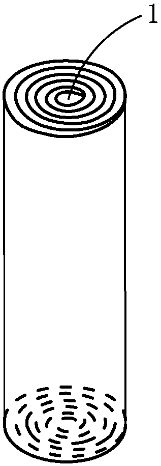
[0031] A flue gas generating section used to form a flue gas generating system. The cylinder body is composed of several hollow pipe bodies with different pipe diameters stacked on the same axis; the outer diameter of the cylinder body is 6-10mm, and the length is 10- 50mm; the coaxial tubular cavity (central tube body) at the center has a diameter of 1-3mm and a length of 10-50mm, and is compatible with the size and specification of the central heating element.

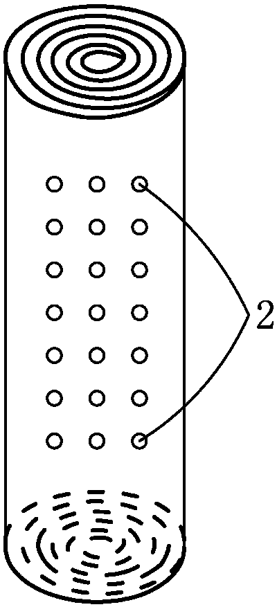
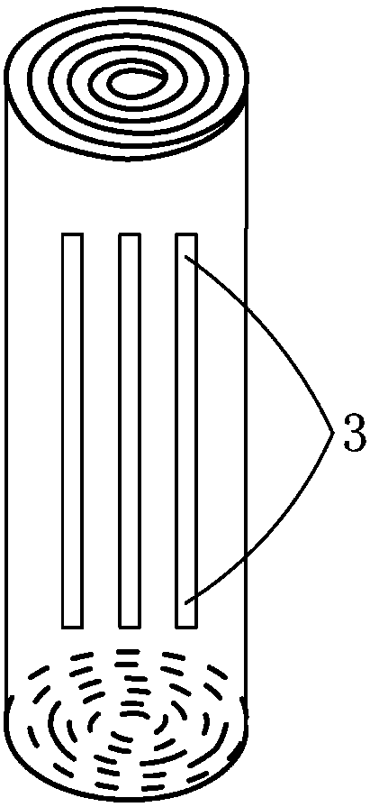
[0032] The pipe body is composed of thin slices connected end to end, and the thin slices are provided with a plurality of circular and / or slit-shaped heat convection holes. And preferably, the heat convection holes are arranged axially, and the heat convection holes of the same horizontal section penetrate from the outer surface of the cylinder to the center of the circle.

[0033] If the thermal convection hole is circular, the diameter is 0.2-1mm, the interval is 1-4mm, and the density is 4-25 / cm 2 .

[0034] If...

Embodiment 2

[0039] A smoke generating section used to form a smoke generating system. The cylinder is composed of several thin slices connected end to end in a spiral shape, and the center is a coaxial tubular cavity; the diameter of the outer ring is 6-10mm, and the length is 10-50mm, the diameter of the coaxial tubular cavity at the center is 1-3mm, and the length is 10mm-50mm, which is compatible with the size and specification of the central heating element. Preferably, several flakes are a whole large flake.

[0040] Several circular and / or slit-shaped heat convection holes are arranged on the sheet. And preferably, the heat convection holes are arranged axially, and the heat convection holes of the same horizontal section penetrate from the outer surface of the cylinder to the center of the circle.

[0041] If the thermal convection hole is circular, the diameter is 0.2-1mm, the interval is 1-4mm, and the density is 4-25 / cm 2 .

[0042] If the thermal convection holes are slot-sh...


PUM


Abstract

The invention discloses a smoke generation section for constituting a smoke generation system. A tube body is formed by a plurality of cavity pipe bodies which are coaxially superposed, wherein the cavity pipe bodies have different pipe diameters; the pipe bodies are constituted by slices which are connected end to end; and a plurality of heat convection holes are formed in the slices. The smoke generation section can be formed by the multiple pipe bodies which are superposed and can also be formed by the slices which are rolled; the diameter of the tube body can be controlled by controlling the length of the slices in the rolling direction; through the multiple heat convection holes, the heat transfer efficiency between a heating element and the smoke generation section and the heat transfer efficiency inside the smoke generation section can be improved, convective heat transfer is enhanced, and the smoke formation effect is improved; through arranged convex patterns, pores between every two adjacent layers of slices can be increased, and thus large smoke channels are formed so as to achieve the better smoke formation effect and smoking feeling; according to the smoke generation section, smoke can be released in a center heating or center and periphery mixed heating mode; and the smoke generation section is simple in structure, few in preparation step, high in efficiency, rapid and convenient to operate and good in effect, and has very high practicability.

Description

technical field [0001] The present invention relates to a smoke generating section, in particular to a smoke generating section for constituting a smoke generating system. Background technique [0002] New forms of business in the tobacco industry are gradually emerging, especially various types of smoke generation systems with electric heating, which have begun to emerge in the market. [0003] The objects of electric heating are divided into liquid and solid. Most of the smoke-forming materials are solid materials, which can release volatile compounds through external heating or combustion heating to form smoke. [0004] As far as solid-state heating objects are concerned, electric heating methods include central heating, surrounding heating, and mixed heating between the center and the surrounding. These electrically heated solid-state smoke generating systems generally include: a smoke generating section, a cooling section, a filter section, and possibly a supporting s...

Claims


Application Information

Patent Timeline
Patent Type & Authority Applications(China)
IPC IPC(8): A24F47/00
CPCA24F47/00
Inventor 刘献军石怀彬李朝建金勇尤晓娟何红梅郭军亮黄伟韩开冬
Owner CHINA TOBACCO JIANGSU INDAL
Why Eureka
Try Eureka