Vacuum sucker type pick-up manipulator

A technology of vacuum suction cups and manipulators, applied in the direction of manipulators, program-controlled manipulators, chucks, etc., which can solve the problems of increased equipment cost, increased installation difficulty, and affecting the speed of the second sheet of material, so as to achieve simple installation and reduce safety. Hidden dangers, the effect of improving production efficiency

Inactive Publication Date: 2019-09-06
高密市瑞力特数控设备有限公司
View PDF0 Cites 2 Cited by
  • Summary
  • Abstract
  • Description
  • Claims
  • Application Information

AI Technical Summary

Problems solved by technology

At present, the way of discharging is that after the wooden boards are put together, they are cut by the cutting saw, and then the wooden board is pushed to the receiving lifting platform at the other end by the push plate of the cutting saw, which takes a long time in the middle and affects the second The speed of two sheets of material is time-consuming and labor-intensive, and the efficiency is offset
[0003] In addition, the material receiving lifting platform meter needs to dig a position pit, about 1.8*1.8*1.8 deep pit, which increases the difficulty of installation
There is also a hydraulic mechanism that is matched with it, which directly leads to an increase in the cost of the equipment. At the same time, it is more labor-intensive, waste materials, electricity consumption, uneven placement, and potential safety hazards in deep pits.

Method used


Image

  • Vacuum sucker type pick-up manipulator
  • Vacuum sucker type pick-up manipulator
  • Vacuum sucker type pick-up manipulator

Examples


Embodiment 1

[0030] Embodiment 1 Vacuum suction cup type pick-up manipulator

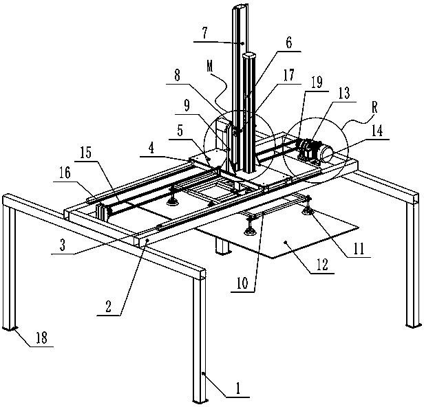
[0031] see Figure 1~8 , the present invention provides a vacuum suction cup-type picking manipulator, comprising a fixed bracket 1, two fixed brackets 1 are symmetrically arranged, and a picking gantry 2 is arranged horizontally on the two fixing brackets 1, and the picking gantry 2 is rectangular border structure.

[0032] The bottom of the fixed bracket 1 is provided with a fixed bracket adjusting plate 18, and the fixed bracket adjusting plate 18 is provided with an adjusting hole. An anchor bolt can be arranged in the adjustment hole to fix the fixing bracket 1 on the ground.

[0033] Both the fixed bracket 1 and the pick-up gantry 2 are composed of square tubes with a side length of 100 mm.

[0034] The frame where the two corresponding long sides on the picking gantry 2 is located is provided with a transverse slide rail 3,

[0035] It also includes a column to pick up and fix the plate 5, and the col...

Embodiment 2

[0058] Embodiment 2 Vacuum suction cup type pick-up manipulator

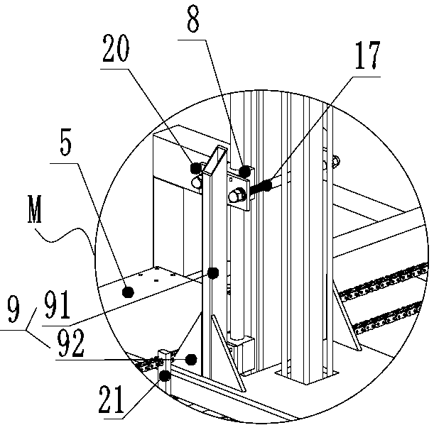
[0059] The present invention also provides a vacuum chuck-type picking manipulator, which is different from the above-mentioned embodiment in that: the fixed mounting plate 9 of the slider includes two symmetrically arranged base plates 91, and right-angles are arranged on both sides of the bottom of each base plate 91 The triangular fixing plate 92 and the right-angled triangular fixing plate 92 can more firmly fix the base plate 91 on the column pick-up fixing plate 5, so that it is not easy to shake.

[0060] The base plate 91 is a rectangular tube, and the top of the base plate 91 is an inclined incision, and the incision is downward from the side close to the central axis of the column picking up the fixing plate 5 to the side away from the central axis of the column picking up the fixing plate 5 Tilt setting. The oblique setting of the cutout can ensure the convenience of observing the conditions on both ...


PUM


Abstract

The invention provides a vacuum sucker type pick-up manipulator. The vacuum sucker type pick-up manipulator comprises a pick-up gantry and a stand column pick-up fixing plate, wherein two corresponding frames on the pick-up gantry are provided with transverse slide rails, the stand column pick-up fixing plate is arranged on the two transverse slide rails in a crossing manner, the stand column pick-up fixing plate is further provided with an air cylinder, the bottom end of the air cylinder is connected to a connecting plate, the connecting plate is further connected with a longitudinal slidingrail, the air cylinder moves to drive the longitudinal sliding rail to move up and down, the bottom of the longitudinal sliding rail is connected with an adjustable pick-up frame, and a vacuum suckerassembly is arranged at the bottom of the adjustable pick-up frame. According to the vacuum sucker type pick-up manipulator, mechanical pickup is realized, manual material pickup is not needed, time and labor are saved, manual work is saved, cost is saved, the installation mode is simple, transportation is easy, production efficiency is improved, suckers can firmly adsorb wood boards, so that theboards do not fall off in the working process, unnecessary potential safety hazards are reduced, the boards are orderly stacked, and the adjustable pick-up frame is telescopic, so that the requirements of the boards with different sizes can be met.

Description

technical field [0001] The invention belongs to the technical field of pick-up and unloading devices for boards of woodworking jigsaw machines, and relates to a pick-up manipulator, in particular to a vacuum suction cup-type pick-up manipulator. Background technique [0002] After the jigsaw machine on the market is finished loading the materials, multiple people work together to lift the cut boards on the ground cage, and then push the boards to the subsequent processing position. At present, the way of discharging is that after the wooden boards are put together, they are cut by the cutting saw, and then the wooden board is pushed to the receiving lifting platform at the other end by the push plate of the cutting saw, which takes a long time in the middle and affects the second The speed at which the two sheets are discharged is time-consuming and labor-intensive, and the efficiency is offset. [0003] In addition, the material-receiving lifting platform meter needs to di...

Claims


Application Information

Patent Timeline
Patent Type & Authority Applications(China)
IPC IPC(8): B25J9/02B25J9/12B25J9/14B25J15/06
CPCB25J9/026B25J9/104B25J9/123B25J9/144B25J15/0616
Inventor 李波
Owner 高密市瑞力特数控设备有限公司
Why Eureka
Try Eureka