Locking structure and tensioning holding component and implementation method and tensioning device for prestressed tendons

A technology for retaining parts and locking structures, applied in the field of rail transit, can solve the problems of frequent replacement of tension retaining structures, failure of friction wheel friction walls, and impact on the performance of track plates, and achieves good effects, increased service life, and simple structure. Effect

Pending Publication Date: 2019-09-06
宁波华铁轨道交通装备制造有限公司 +1
View PDF1 Cites 1 Cited by
  • Summary
  • Abstract
  • Description
  • Claims
  • Application Information

AI Technical Summary

Problems solved by technology

[0002] In the past, in the production process of high-speed rail track slabs, whether it is pre-tensioning or post-tensioning, artificial single-stretched prestressed steel bars are used, such as figure 1 As shown, the ends of several prestressed steel bars arranged in the track slab mold 1 are connected with tension rods 2, and the tension rods 2 extend outside the wall of the track slab mold 1. In this way, all the prestressed steel bars on the track slab mold 1 are tensioned The degree of pull is different, which will affect the performance of the track slab and even lead to the scrapping of the track slab; in order to overcome the above problems and improve the automation level of the track slab production, the production line of the track slab unit assembly line is now used, such as figure 2 As shown, all the prestressed steel bars on one side of the track slab are stretched synchronously by the tensioner 3. After the tension is in place, a tension anchor component is set between the tension rod 2 and the wall of the track slab mold 1 to maintain the tension state
[0003] The Chinese patent application with the publication number CN109262827A discloses a tensioning

Method used


Image

  • Locking structure and tensioning holding component and implementation method and tensioning device for prestressed tendons
  • Locking structure and tensioning holding component and implementation method and tensioning device for prestressed tendons
  • Locking structure and tensioning holding component and implementation method and tensioning device for prestressed tendons

Examples


Embodiment 1

[0074] like Figure 3-5 As shown, a locking structure of the present invention includes a helical gear nut 21 and a helical gear 41 capable of meshing with it. The helical gear nut 21 is a round nut with internal threads, and the outer wall of the round nut is provided with helical teeth. .

[0075] The helical gear nut 21 is used to be threadedly connected to the component to be locked, the axis of the helical gear nut 21 and the axis of the helical gear 41 are arranged perpendicular to each other, and the helical gear 41 is used to drive the helical gear nut 21 to rotate , the helical gear 41 can move along its axial direction.

[0076] The locking structure is realized in such a way that the helical gear nut 21 and the helical gear 41 engage and rotate, and the helical gear nut 21 rotates to the component to be locked along its axial direction, when the helical gear nut After 21 fits on the parts to be locked, that is, after reaching the locked state, the helical gear nut...

Embodiment 2

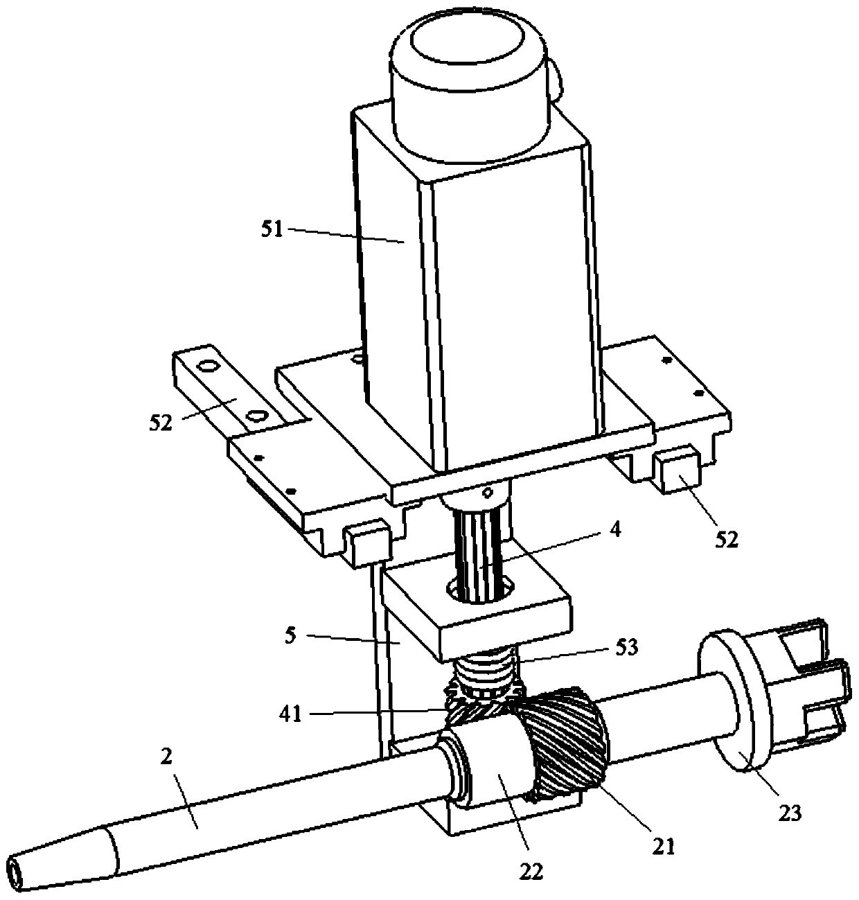
[0079] like Figure 3-6 As shown, a prestressed tendon tension holding part according to the present invention includes a locking structure as described in Embodiment 1, a rotating shaft 4, a base 5, a first drive assembly 51, a slide rail 52, a first Two driving components and an elastic mechanism 53, the helical gear nut 21 is used to be threadedly connected to the external thread section 22 of the tension rod 2.

[0080] The helical gear 41 is slidably socketed on the rotating shaft 4, the rotating shaft 4 can drive the helical gear 41 to rotate, the first driving assembly 51 is arranged on the base 5, and the rotating shaft 4 is arranged on The base 5 is connected to the output end of the first drive assembly 51, the first drive assembly 51 is used to drive the rotation of the rotating shaft 4, and the base 5 is slidably adapted to the slide rail 52, the second drive assembly is connected to the base 5 and drives the base 5 to move along the slide rail 52, and one end of ...

Embodiment 3

[0088] like Figure 3-6 As shown, a method for realizing tension retention of prestressed tendons according to the present invention uses the tension retention components as described in Embodiment 2, comprising the following steps:

[0089] A. Pulling the tension rod 2 drives the tensioning of the prestressed steel bars;

[0090] B. The first drive assembly 51 drives the rotating shaft 4 to rotate, so that the helical gear 41 rotates, and the second drive assembly drives the base 5 to move along the slide rail 52, so that the helical gear 41 Close to the helical gear nut 21;

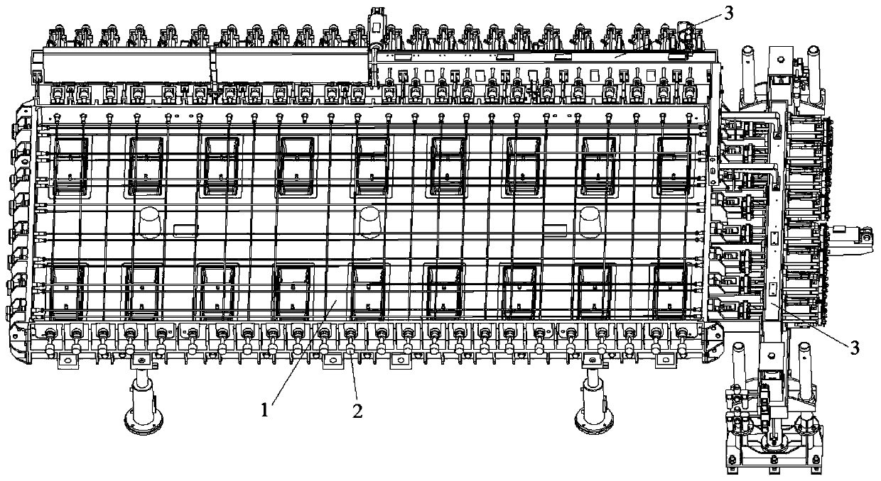
[0091] C. The helical gear 41 meshes with the helical gear nut 21, and the helical gear nut 21 rotates along the external thread section 22 and rotates to the wall of the track plate mold 1;

[0092] D. The helical gear nut 21 is attached to the wall of the track plate mold 1, the helical gear nut 21 stops rotating, the helical gear 41 is in a rotating state, and the helical teeth on the helical gear ...


PUM


Abstract

The invention discloses a locking structure and a tensioning holding component and implementation method and tensioning device for prestressed tendons. The locking structure comprises a bevel gear nutand a bevel gear capable of being engaged with the bevel gear nut. The bevel gear nut is used for being in threaded connection to a to-be-locked component. An included angle is formed between the axis of the bevel gear nut and the axis of the bevel gear and is larger than 0 degrees and smaller than or equal to 90 degrees. The bevel gear is used for driving the bevel gear nut to rotate and can move in the axial direction of the bevel gear nut. By means of the structure, initial alignment of the bevel gear and the bevel gear nut and screwing of the bevel gear nut can be guaranteed, after beingscrewed in place, the bevel gear can be separated from the engaged state and does not continue to be screwed, wear of threads on the bevel gear nut and the to-be-locked component and wear of teeth onthe bevel gear nut and the bevel gear are greatly reduced, the locking effect is guaranteed by achieving good tightening, meanwhile, the service life of each component is prolonged, and the number oftimes of replacement and the use cost are reduced; and the locking structure is simple in structure, convenient to use and good in effect.

Description

technical field [0001] The invention relates to the technical field of rail transit, in particular to a locking structure, a prestressed tendon tensioning and holding component, a realization method and a tensioning device. Background technique [0002] In the past, in the production process of high-speed rail track slabs, whether it is pre-tensioning or post-tensioning, artificial single-stretched prestressed steel bars are used, such as figure 1 As shown, the ends of several prestressed steel bars arranged in the track slab mold 1 are connected with tension rods 2, and the tension rods 2 extend outside the wall of the track slab mold 1. In this way, all the prestressed steel bars on the track slab mold 1 are tensioned The degree of pull is different, which will affect the performance of the track slab and even lead to the scrapping of the track slab; in order to overcome the above problems and improve the automation level of the track slab production, the production line o...

Claims


Application Information

Patent Timeline
IPC IPC(8): B28B23/04
CPCB28B23/04
Inventor 娄景辉吴元文税卓平赖旭洋
Owner 宁波华铁轨道交通装备制造有限公司
Why Eureka
Try Eureka