
Universal joint structure of steel structure X-beam Y-shaped column

A technology for node structure and steel structure, which is applied in building construction, construction, etc., can solve problems such as self-heavy weight, steel structure truss installation and adverse effects of wind resistance.

Inactive Publication Date: 2019-09-06
ZHONGYUAN ENGINEERING COLLEGE
View PDF17 Cites 3 Cited by
  • Summary
  • Abstract
  • Description
  • Claims
  • Application Information

AI Technical Summary

Problems solved by technology

[0004] However, when the seat body is lifted by the traction force of the rotating core body and is in the middle position, because the seat body is suspended in the air, and in order to ensure that the seat body is sufficiently wear-resistant, its own weight is relatively large, so after the adjustment is in place, the seat body will exert a pull-down effect on the rotating core body The pull-down force will generate bending and torsional stress on the steel structure truss, which will have an adverse effect on the installation and wind resistance of the steel structure truss

Method used


Image

  • Universal joint structure of steel structure X-beam Y-shaped column
  • Universal joint structure of steel structure X-beam Y-shaped column

Examples


Embodiment Construction

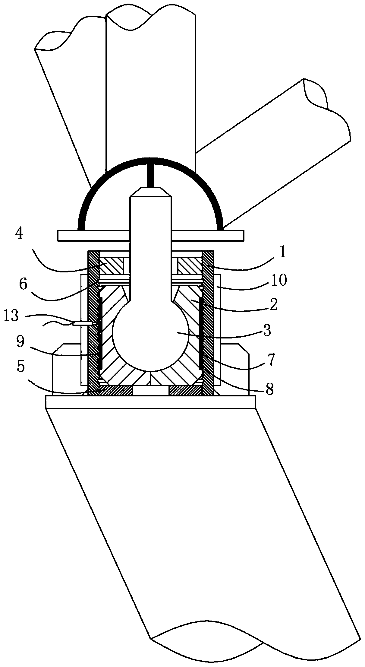
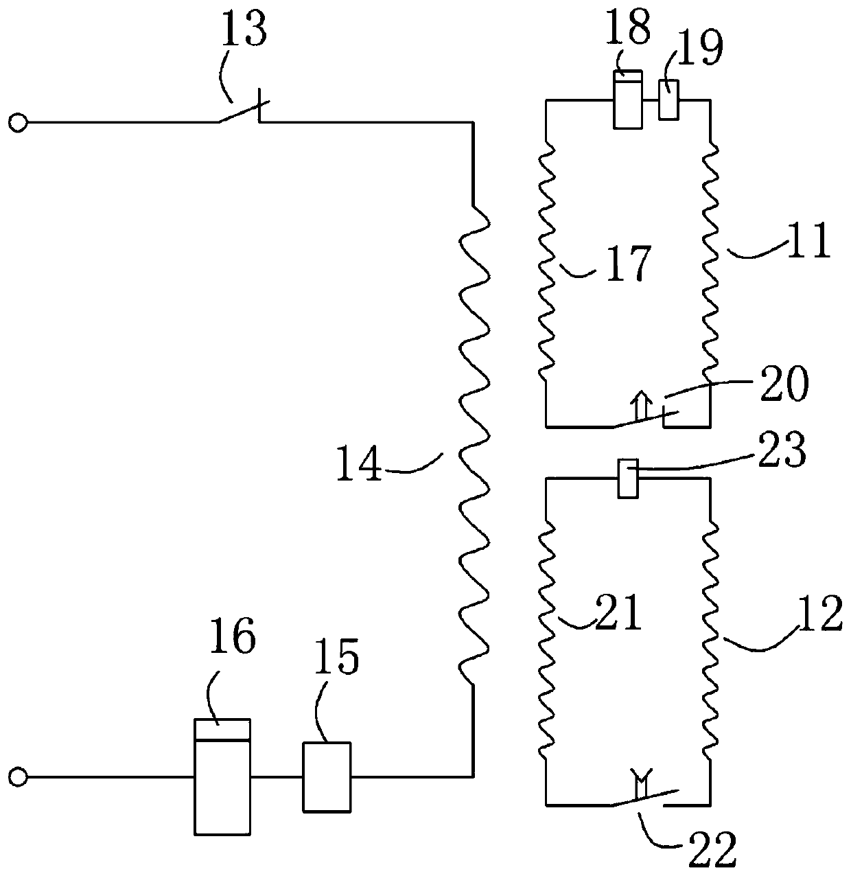
[0013] see figure 1 , shows a schematic structural view of the universal joint structure of the steel structure X-beam Y-shaped column of the present invention. The node structure is not located at the connection position between the steel structure and the ground foundation, but between the beams and columns of the truss, especially the multi-bar connection node shown in the figure, that is, the node structure is located between the main support beam column and the first branch beam column, the first branch beam column, and the second branch beam column. At the connection position of the beam-column of the second branch and the beam-column of the third branch, the connection form of universal ball joint commonly used in steel structure trusses is adopted. At the same time, combined with the automobile piston type up and down adjustment structure, it can ensure that the node structure realizes three-dimensional multi-directional stress unloading adjustment. The specific struc...


PUM


Abstract

The invention relates to a universal joint structure of a steel structure X-beam Y-shaped column. A layered or spirally distributed limiting groove is formed in one of the outer wall of a seat body and the inner wall of a sleeve body, a bulge-shaped annular sac filled with magnetorheological fluid on the inside is mounted on the other in an embedded mode, wherein the exposed side of the bulge-shaped annular sac is capable of being elastically embedded in the limiting groove, the sleeve body is provided with an electromagnetic coil surrounding a stroke section of the seat body, and the electromagnetic coil is connected to a mains supply or an energy storage device through a control switch. The characteristic that the magnetorheological fluid is in a fluid state in an unenergized state is used for facilitatingupward and downward movements of the seat body for positional adjustment; after the seat body moves to a set position, the electromagnetic coil around the magnetorheological fluid is continuously energized, the magnetic field generated by the electromagnetic coil prompts the magnetorheological fluid to change into a solid state and be locked on the limiting groove to realize thein-position locking function of the seat body, stress applied to a transverse frame by the seat body is reduced, thus the stress between a steel frame truss beam and column is reduced, and wind resistance reliability and mounting convenience are improved.

Description

technical field [0001] The invention belongs to the field of steel structure buildings, in particular to a universal joint structure of an X-beam Y-shaped column of a steel structure. Background technique [0002] In modern steel structure buildings, there are often structures that require hinged joints between column tops and beams. At present, most of the designs for such hinged joints use bolts to meet the requirements of approximate hinged joints. In addition to transmitting all shear forces, bolts also Transfer a small amount of bending moment in-plane and out-of-plane that is not released. With the development of social economy, more and more large-span, inclined column tops and beam hinged structures appear. In such structures, the method of setting a small number of bolts to achieve approximate hinged joints has not reached the current hinged joints. Requirements, because on the nodes of this type of structure, the node rotation angle is relatively large, and the to...

Claims


Application Information

Patent Timeline
Patent Type & Authority Applications(China)
IPC IPC(8): E04B1/344
CPCE04B1/3441
Inventor 楚金祎黄开勇
Owner ZHONGYUAN ENGINEERING COLLEGE
Learn More