A shaft cutter head, a shaft boring machine and a shaft drilling rig

A cutterhead and shaft technology, which is applied in the field of shaft cutterheads and shaft drilling rigs, can solve the problems of low efficiency, time-consuming scraper, and affecting shaft excavation efficiency.

Active Publication Date: 2021-08-10
CHINA RAILWAY CONSTR HEAVY IND
View PDF13 Cites 0 Cited by
  • Summary
  • Abstract
  • Description
  • Claims
  • Application Information

AI Technical Summary

Problems solved by technology

[0003] Since the excavation direction of the shaft cutter head is consistent with the direction of gravity, the muck cannot be gathered automatically. In the prior art, the transmission mechanism drives the scraper to move to the central area, so that the muck gathers to the central area, but the scraper is in the process of bulldozing. In the process, the slag is easy to leak from both sides of the scraper, and the moving process of the scraper takes a certain amount of time, resulting in poor slag cleaning effect and low efficiency of the existing shaft cutter head, which affects the excavation efficiency of the shaft

Method used


Image

  • A shaft cutter head, a shaft boring machine and a shaft drilling rig
  • A shaft cutter head, a shaft boring machine and a shaft drilling rig
  • A shaft cutter head, a shaft boring machine and a shaft drilling rig

Examples


Embodiment Construction

[0031] The following will clearly and completely describe the technical solutions in the embodiments of the present invention with reference to the accompanying drawings in the embodiments of the present invention. Obviously, the described embodiments are only some, not all, embodiments of the present invention. Based on the embodiments of the present invention, all other embodiments obtained by persons of ordinary skill in the art without making creative efforts belong to the protection scope of the present invention.

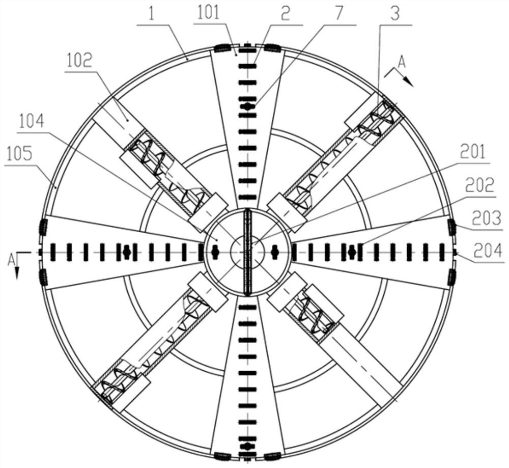
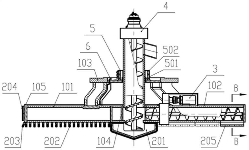
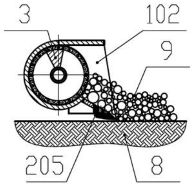
[0032] The core of the present invention is to provide a shaft cutter head, which can effectively improve the cleaning quality and cleaning efficiency of muck. Another core of the present invention is to provide a shaft boring machine including the above-mentioned shaft cutter head and a shaft drilling machine including the above-mentioned shaft cutter head.

[0033] Please refer to Figure 1-3 , figure 1 It is a structural schematic diagram of a specific em...


PUM


Abstract

The invention discloses a shaft cutterhead, which comprises a cutterhead body, a spoke screw machine for gathering the dregs in the non-central area of ​​the face of the shaft to the central area, and a central auger for outputting the dregs in the central area The central screw machine is arranged at the center of the cutter body, and the spoke screw machines are arranged radially on the outer periphery of the central screw machine; and both the central screw machine and the spoke screw machines are connected with the cutter body. Since the muck is transported by the center screw machine and the spoke screw machine in this application, the problem of the muck leaking from both sides of the scraper is avoided during the transportation process, and the continuous transportation of the muck can be realized, making the muck The transportation efficiency and cleaning quality are improved, which can effectively improve the slag cleaning effect. In addition, the present invention also discloses a shaft boring machine including the above-mentioned shaft cutter head and a shaft drilling machine including the above-mentioned shaft cutter head.

Description

technical field [0001] The present invention relates to the technical field of full-face shaft boring machines, and more specifically, relates to a shaft cutterhead; in addition, the present invention also relates to a shaft boring machine including the above-mentioned shaft cutterhead and a shaft including the above-mentioned shaft cutterhead rig. Background technique [0002] At present, in order to mine underground minerals, it is usually necessary to build shafts on the surface of the ground. Traditional shaft excavation methods include grouting, freezing, and blasting. Compared with the above traditional methods, shaft boring machines are more and more widely used in shaft construction projects because of their safety and high efficiency. The cutter head is the key equipment of the shaft boring machine. Its main function is to realize the excavation of the face of the shaft and to form the entire section of the shaft at one time. [0003] Since the excavation directio...

Claims


Application Information

Patent Timeline
Patent Type & Authority Patents(China)
IPC IPC(8): E21D1/06E21D1/00
CPCE21D1/00E21D1/06
Inventor 刘飞香程永亮何其平暨智勇姚满柯威阳旭
Owner CHINA RAILWAY CONSTR HEAVY IND
Why Eureka
Try Eureka