Dynamic balance process method of carbon fiber composite transmission shaft tube and combined dynamic balance clamping hoop

A composite material and process method technology, applied in the field of shaft dynamic balance, to achieve the effects of strong operability, avoidance of weak bonding, and simple processing and manufacturing process

Inactive Publication Date: 2019-09-06
WUHAN UNIV OF TECH
13 Cites 3 Cited by

AI-Extracted Technical Summary

Problems solved by technology

This method is simple to operate, solves the dynamic balance problem of car...

Abstract

The invention discloses a process method for achieving dynamic balance of a carbon fiber composite transmission shaft and a used combined dynamic balance clamping hoop device. The dynamic balance device comprises a clamping hoop, bolts, nuts, spring gaskets, balancing weights and balancing weight set screws. The clamping hoop is composed of four quarter round clamping hoop bodies which are connected through the bolts, the nuts and the spring gaskets. The integrated round clamping hoop is formed on a carbon fiber composite tube in the circumferential direction. Threaded holes used for fixing the balancing weights are uniformly distributed in the circumference of the round clamping hoop. The device is simple in structure, the carbon fiber composite transmission shaft can be dynamically balanced by adopting a weight increment method or a weight decrement method by means of the process method, in addition, operation is convenient when the axial and circumferential positions of the balancing weights are adjusted, drilling weight-decrement is not needed in the carbon fiber composite transmission shaft, the balancing weights do not need to be bonded to the shaft, and dynamic balance of the carbon fiber composite shaft tube can be easily and effectively achieved.

Application Domain

Vibration dampersSprings +5

Technology Topic

Carbon fiber compositeFibrous composites +6

Image

  • Dynamic balance process method of carbon fiber composite transmission shaft tube and combined dynamic balance clamping hoop

Examples

  • Experimental program(1)

Example Embodiment

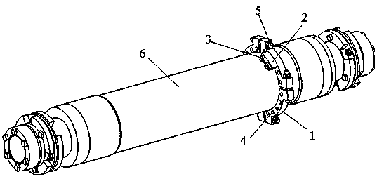
[0020] The present invention will be further described below in conjunction with the accompanying drawings, but is not limited to the content described below.
[0021] Referring to Fig. 1, it is a diagram of the overall structure of the hoop involved in a method for realizing the dynamic balance of the carbon fiber composite shaft tube of the present invention, including the hoop 1, bolts, nuts and spring washers 5. Among them, the clamp 1 is composed of four quarter-circle clamps, and the quarter-circle clamps are composed of bolts, nuts and spring washers 5 (the spring washers are placed between two adjacent quarter-circle clamps). The bolts of a round clamp and then fastened with nuts) are connected to form a complete circular clamp 1.
[0022] On the circumference of the complete circular clamp 1 (the side or axial surface of the clamp 1), some threaded holes 4 are evenly arranged (the axis of the threaded hole is parallel to the axis of the clamp), and the number of threaded holes 4 can be set according to needs . Each threaded hole 4 is correspondingly provided with a fixing screw 3, and the fixing screw 3 can fasten an appropriate counterweight 2.
[0023] The present invention realizes the dynamic balancing process of the carbon fiber composite transmission shaft tube, and the combined dynamic balance clamp including the clamp and the counterweight is fixedly connected to the carbon fiber composite transmission shaft, and the number of counterweights is increased one by one. , to detachably fix the counterweight at different positions of the hoop until the dynamic balance of the carbon fiber composite shaft is achieved; or, the combined dynamic balance hoop including the hoop and the counterweight is fixedly connected to the carbon fiber composite transmission shaft Above, the counterweights are detachably fixed at different positions of the hoop, and the number of counterweights is reduced one by one until the dynamic balance of the carbon fiber composite shaft is achieved.
[0024] In the implementation of weight gain, when adjusting the dynamic balance of the carbon fiber composite material shaft tube, the clamp 1 can be installed on the appropriate axial position of the carbon fiber composite material shaft tube 6 through an interference connection, and then the counterweight can be increased one by one on the threaded hole 4 The number of blocks 2 is adjusted and the circumferential position is adjusted to realize the dynamic balance of the carbon fiber composite shaft tube.
[0025] In the weight-removing implementation mode, when adjusting the dynamic balance of the carbon fiber composite shaft tube, all the threaded holes 4 can be fitted with counterweights 2, and then the number of counterweights 2 can be reduced one by one to realize the dynamic balance of the carbon fiber composite shaft tube.
[0026] The above disclosures are only a few specific embodiments of the present application, but the present application is not limited thereto, and any changes conceivable by those skilled in the art shall fall within the protection scope of the present application.
[0027] The manufacturing process of the metal clamp of the present invention is simple, and the dynamic balance counterweight is realized through mechanical connection, so as to avoid weak bonding; the dynamic balance of the carbon fiber composite transmission shaft is realized by using the clamp, and the integrity of the material of the carbon fiber composite transmission shaft will not be damaged. , will not change the strength of the shaft; the dynamic balance of the carbon fiber composite transmission shaft can be achieved by using the clamp, which can be achieved by either increasing or decreasing the method or removing the weight, and the operation is simple.

PUM

no PUM

Description & Claims & Application Information

We can also present the details of the Description, Claims and Application information to help users get a comprehensive understanding of the technical details of the patent, such as background art, summary of invention, brief description of drawings, description of embodiments, and other original content. On the other hand, users can also determine the specific scope of protection of the technology through the list of claims; as well as understand the changes in the life cycle of the technology with the presentation of the patent timeline. Login to view more.

Similar technology patents

Prism coupling type wedge-shaped plane waveguide optical device

ActiveCN104536139ASimple manufacturing processCompact and flexible
Owner:上海理湃光晶技术有限公司

Classification and recommendation of technical efficacy words

  • Simple manufacturing process
Why Eureka
Try Eureka