
Movable gas supply cabinet

A mobile, gas cabinet technology, used in motor vehicles, gas/liquid distribution and storage, trolleys, etc., can solve the problems of cumbersome gas cylinders, troublesome mixing of gas into experimental devices or workstations, and achieve the effect of ensuring safety.

Inactive Publication Date: 2019-09-06
SHENZHEN RONGKE SEMICON EQUIP CO LTD
View PDF10 Cites 2 Cited by
  • Summary
  • Abstract
  • Description
  • Claims
  • Application Information

AI Technical Summary

Problems solved by technology

[0003] At present, no matter in the laboratory or research institute, there is no device that can directly mix multiple gases, and the gas cylinder is very heavy. In actual operation, various mixed gases are sent into the experimental device or work station Therefore, in view of the above status quo, it is urgent to develop a mobile gas supply cabinet to overcome the deficiencies in current practical applications

Method used


Image

  • Movable gas supply cabinet
  • Movable gas supply cabinet
  • Movable gas supply cabinet

Examples


Embodiment 1

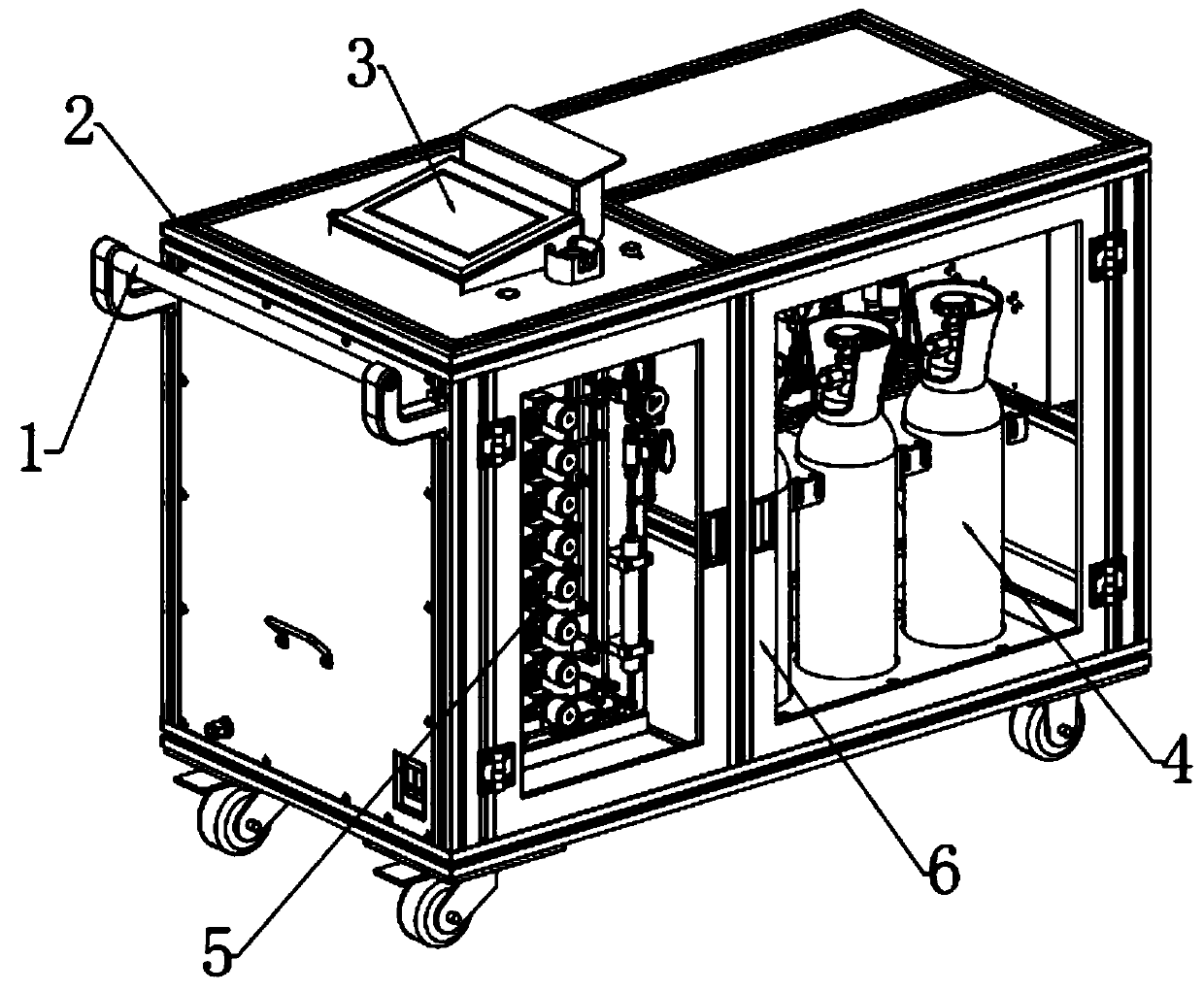
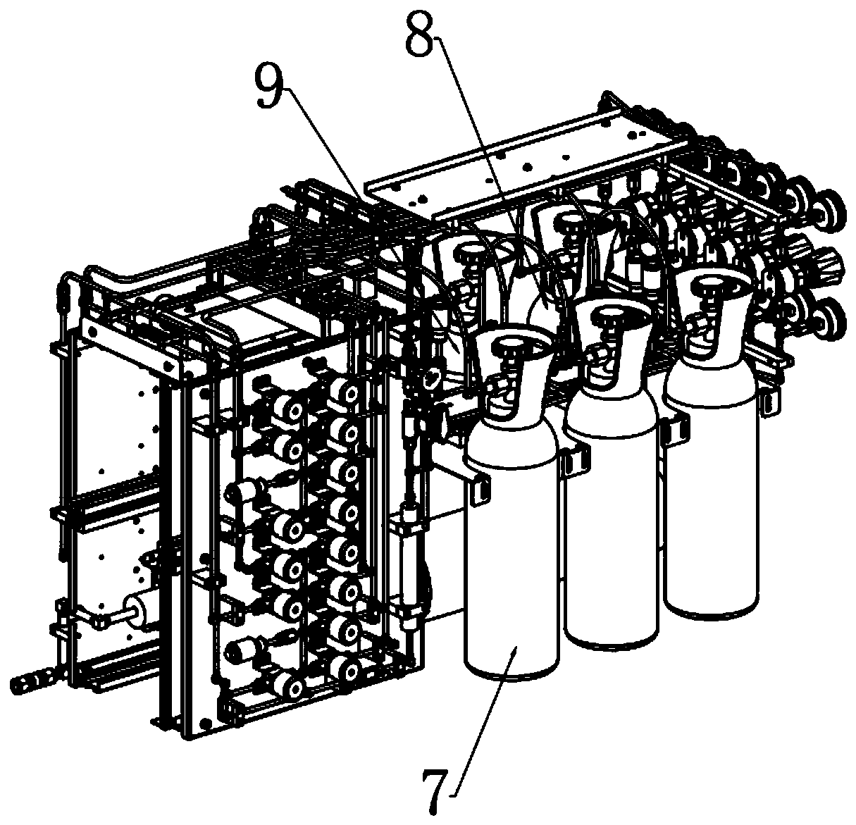
[0026] see Figure 1~3 , in an embodiment of the present invention, a mobile gas supply cabinet includes a vehicle frame 2, a push rod 1 is fixedly connected to the top left side of the vehicle frame 2, and a steel cylinder storage bin 4 is provided at the inner right end of the vehicle frame 2, The left side of the steel cylinder storage bin 4 is provided with an operation control bin 5, the top of the frame 2 is provided with a touch screen 3, the touch screen 3 is connected to the controller, and the bottom of the frame 2 is bolted to be provided with casters. And push rod 1, can make things convenient for people to move vehicle frame 2, make the place of use of device unrestricted, described cylinder storage bin 4 and operation control bin 5 front sides are all provided with the car door 6 that is hinged with vehicle frame 2.

[0027] In this embodiment, the frame 2 is made of stainless steel.

Embodiment 2

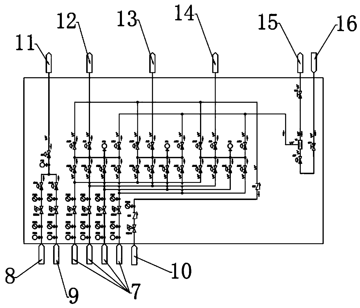
[0029] In this embodiment, a special gas cylinder 7, a first steel cylinder 8, a second steel cylinder 9 and a third steel cylinder 10 are arranged in the steel cylinder storage bin 4, COA is arranged in the first steel cylinder 8, and the second steel cylinder 9 is set with N 2 , the third cylinder 10 is provided with purge gas for purging the mixing pipeline, and the special gas cylinder 7 is provided with special gas.

[0030] In this embodiment, the number of the special gas cylinders 7 is four, and the gases in the four special gas cylinders 7 are all different.

[0031] In this embodiment, the operation control chamber 5 includes several pressure sensors, pressure gauges and pressure regulating valves corresponding to the special gas cylinder 7 , the first cylinder 8 , the second cylinder 9 and the third cylinder 10 .

[0032] In this embodiment, a first air outlet 11, a second air outlet 12, a third air outlet 13, and a fourth air outlet 14 are provided inside the oper...


PUM


Abstract

The invention relates to the technical field of gas supply, in particular to a movable gas supply cabinet. The movable gas supply cabinet comprises a frame. A push rod is fixedly connected to the topend of the left side of the frame. A cylinder storage bin is arranged at the right end of the frame. An operation control bin is arranged on the left side of the cylinder storage bin. A touch screen is arranged on the top of the frame. The touch screen is connected with a controller. Casters are connected to the bottom of the frame through bolts. According to the movable gas supply cabinet, by arranging the casters and the push rod, it is convenient for people to move the frame, so that the use location of the device is not limited; by arranging the operation control bin, six kinds of high-purity gases can be mixed according to different proportions and are correspondingly supplied to four gas points; by arranging a vacuum generator, nitrogen gas is introduced into an intake pipe to generate a negative pressure on the bypass side of the vacuum generator, so that the gas in each branch is exhausted; and by adopting fully automatic control, the safety of an operator and the environment can be ensured.

Description

technical field [0001] The invention relates to the technical field of gas supply, in particular to a mobile gas supply cabinet. Background technique [0002] When conducting experimental research in laboratories and research institutes, various gases with different components and different proportions are often used. Steel cylinders for storing gases during the gas supply process are common equipment. Steel cylinders are generally used to hold permanent gases, Liquefied gas or mixed gas. [0003] At present, no matter in the laboratory or research institute, there is no device that can directly mix multiple gases, and the gas cylinder is very heavy. In actual operation, various mixed gases are sent into the experimental device or work station It is very troublesome, therefore, in view of the above status quo, there is an urgent need to develop a mobile gas supply cabinet to overcome the deficiencies in current practical applications. Contents of the invention [0004] T...

Claims


Application Information

Patent Timeline
Patent Type & Authority Applications(China)
IPC IPC(8): F17C13/08B62B3/10
CPCB62B3/104B62B2202/022F17C13/08F17C2205/0161F17C2205/0165
Inventor 刘书田郑少宾可建
Owner SHENZHEN RONGKE SEMICON EQUIP CO LTD
Learn More