
An automatic centering adjustment system of an engine stand

An engine bench, automatic centering technology, which is applied in the direction of engine testing, machine/structural component testing, instruments, etc. High precision and ensure the effect of safety

Active Publication Date: 2021-12-14
TAIYUAN UNIV OF TECH
View PDF19 Cites 0 Cited by
  • Summary
  • Abstract
  • Description
  • Claims
  • Application Information

AI Technical Summary

Problems solved by technology

[0002] When traditional car companies and research institutes conduct engine bench experiments, engine alignment is often a headache for the experimenters. When changing different engine experiments, due to the different sizes of the engine bases, the flywheel shaft and dynamometer after the engine is replaced The shafts are not on the same axis, so the engine needs to be centered. In the traditional engine centering, the experimenter uses a dial indicator to determine the position of the end surface of the engine flywheel and the circumferential direction, and then uses a sledgehammer to hit the lower support of the engine to change the position of the engine. Then use a dial gauge to measure the position of the engine flywheel, and change the position after multiple measurements and sledgehammer knocking until the engine flywheel shaft and the dynamometer shaft are aligned. This method wastes time and increases the labor of the experimenters. manual labor

Method used


Image

  • An automatic centering adjustment system of an engine stand
  • An automatic centering adjustment system of an engine stand
  • An automatic centering adjustment system of an engine stand

Examples


Embodiment Construction

[0016] In order to make the purpose, technical solutions and advantages of the embodiments of the present invention clearer, the technical solutions in the embodiments of the present invention will be clearly and completely described below. Obviously, the described embodiments are part of the embodiments of the present invention, rather than All the embodiments; based on the embodiments of the present invention, all other embodiments obtained by persons of ordinary skill in the art without creative work all belong to the protection scope of the present invention.

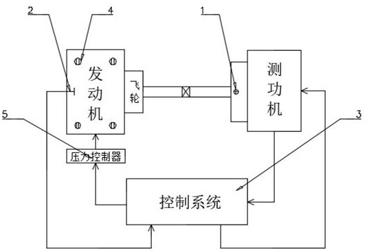
[0017] Such as figure 1 As shown, the embodiment of the present invention provides an automatic centering adjustment system for an engine stand, including a stand base, a laser sensor 1, a control system 3 and a pressure controller 5; the stand base is provided with a three-dimensional translation mechanism, The engine is fixed on the base of the platform through a three-dimensional translation mechanism, the laser ...


PUM


Abstract

The invention provides an automatic centering adjustment system for an engine stand, comprising a stand base, a laser sensor, a control system and a pressure controller; On the base, the laser sensor is fixed above the shaft of the dynamometer, and the vibration recognition sensor is fixed on the base of the bench. The signal output terminals of the laser sensor and the vibration recognition sensor are connected to the control system, and the output terminal of the control system is connected to the pressure controller. Connection; the control system is used to calculate the position information of the engine relative to the dynamometer according to the information sent by the laser sensor, and send the control signal to the pressure controller. The pressure controller is used to control the three-dimensional translation according to the control signal sent by the control system The mechanism moves to center the engine. The invention can realize the automatic centering of the engine bench, and can be widely used in the field of engine test benches.

Description

technical field [0001] The invention belongs to the field of engine test benches, and in particular relates to an automatic centering adjustment and monitoring system of an engine bench for experiments. Background technique [0002] When traditional car companies and research institutes conduct engine bench experiments, engine alignment is often a headache for the experimenters. When changing different engine experiments, due to the different sizes of the engine bases, the flywheel shaft and dynamometer after the engine is replaced The shafts are not on the same axis, so the engine needs to be centered. In the traditional engine centering, the experimenter uses a dial indicator to determine the position of the end surface of the engine flywheel and the circumferential direction, and then uses a sledgehammer to hit the lower support of the engine to change the position of the engine. Then use a dial gauge to measure the position of the engine flywheel, and change the position...

Claims


Application Information

Patent Timeline
Patent Type & Authority Patents(China)
IPC IPC(8): G01M15/02
CPCG01M15/02
Inventor 朱建军孙文军张翠平张岩李耀宗李玉峰王子玉
Owner TAIYUAN UNIV OF TECH
Learn More