
Power amplifier based on comb filtering

A technology of power amplifier and comb filter, which is applied in the field of power amplifier based on comb filter, can solve the problems of insignificant harmonic suppression effect, high collector breakdown voltage of power amplifier tube, unfavorable miniaturization, etc. The effects of modernization and integration, suppression of harmonic components, and good practical value

Pending Publication Date: 2019-09-06
LIAONING TECHNICAL UNIVERSITY
View PDF4 Cites 5 Cited by
  • Summary
  • Abstract
  • Description
  • Claims
  • Application Information

AI Technical Summary

Problems solved by technology

If the harmonic components are not recovered and suppressed, it will not only cause waste of energy, reduce its efficiency, but also cause interference to signals of other channels
[0003] Usually, the power amplifier works in class F in order to obtain higher efficiency and lower harmonic components, but this structure requires the use of λ / 4 transmission lines, which occupy a large space, which is not conducive to miniaturization and has poor harmonic suppression effect. obvious
A low-pass output matching network is used to design a power amplifier working in class E, which requires the power amplifier tube to have a high collector breakdown voltage, which is contrary to the development trend of integrated circuits and the harmonic suppression effect is not good.
The power amplifier designed by GaN technology, in order to obtain better harmonic performance, the design introduces two open transmission lines in the output matching network, but the use of open transmission lines makes this method compatible with modern circuits to the direction of miniaturization and high integration Development contradicts

Method used


Image

  • Power amplifier based on comb filtering
  • Power amplifier based on comb filtering

Examples


Embodiment Construction

[0015] The specific implementation of the present invention will be described in detail below in conjunction with the accompanying drawings. As a part of this specification, the principles of the present invention will be described through examples. Other aspects, features and advantages of the present invention will become clear through the detailed description. In the referenced drawings, the same reference numerals are used for the same or similar components in different drawings.

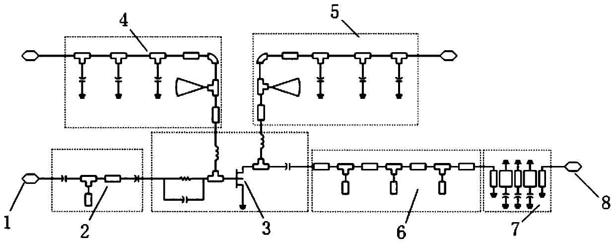
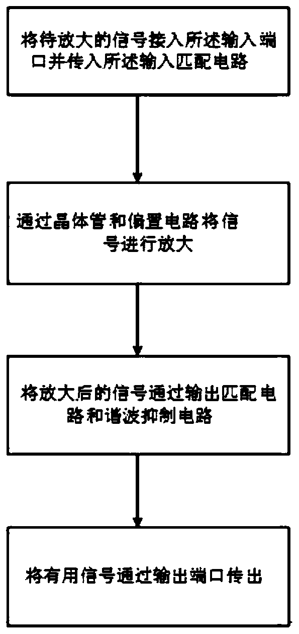
[0016] Such as Figure 1-2 As shown, the comb filter-based power amplifier provided by the present invention includes an input port 1, an input matching circuit 2, a transistor 3, a gate bias circuit 4, a drain bias circuit 5, an output matching circuit 6, and a harmonic suppression Circuit 7, output port 8, wherein, the input port 1, input matching circuit 2, gate bias circuit 4, drain bias circuit 5, transistor 3, output matching circuit 6, harmonic suppression circuit 7, output port 8 are co...


PUM


Abstract

The invention discloses a power amplifier based on comb filtering. The power amplifier comprises an input port, an input matching circuit, a biasing circuit, a transistor, an output matching circuit,a harmonic suppression circuit and an output port which are sequentially connected; a signal to be amplified is connected to the input port and is transmitted to the input matching circuit, and the signal is amplified through the biasing circuit and the transistor; and the amplified signal is filtered by the output matching circuit and the harmonic suppression circuit, and the filtered signal is transmitted to a signal receiving device through the output port. According to the invention, higher harmonics of the power amplifier are mainly suppressed; harmonic energy generated by the power amplifier is recovered through combination of the comb-shaped harmonic suppression circuit and the output matching network. The power amplifier is simple in structure, suppresses harmonic components at a load, guarantees the efficiency of the power amplifier, enables the power amplifier to be easy to realize, achieves the purpose of high efficiency, facilitates miniaturization and integration of a communication system, and has very good practical value.

Description

technical field [0001] The invention belongs to the technical field of communication, in particular to a power amplifier based on comb filtering. Background technique [0002] With the rapid development and wide popularization of wireless communication, wireless system standards have higher and higher performance requirements for transceivers. The power amplifier is the main component of the transmitter, and its indicators determine the performance of the transmitter. For example, the efficiency determines the power consumption of the whole machine, the linearity determines the dynamic range of the whole machine, and the size of the harmonic component is the measure of the linearity of the transmitter. . In order to obtain higher efficiency in traditional power amplifiers, the power amplifier tube usually works in a saturated state, and a large number of harmonic components will be generated at this time. If the harmonic components are not recovered and suppressed, it will...

Claims


Application Information

Patent Timeline
IPC IPC(8): H03F1/02H03F1/56H03F3/213
CPCH03F1/0205H03F1/56H03F3/213
Inventor 南敬昌陶成健高明明黄飞
Owner LIAONING TECHNICAL UNIVERSITY
Learn More