Method and device in communication node for wireless communication

A wireless communication and communication node technology, applied in wireless communication, sustainable communication technology, connection management, etc., can solve the problem of resource utilization reduction and other issues

Active Publication Date: 2019-09-06
SHANGHAI LANGBO COMM TECH CO LTD
View PDF9 Cites 1 Cited by
  • Summary
  • Abstract
  • Description
  • Claims
  • Application Information

AI Technical Summary

Problems solved by technology

Since the process of beam management (beam management) after beam training (beam training) has not been performed in the ungranted uplink transmission in the unconnected state, the problem of resource utilization reduction caused by beam sweeping will be more prominent

Method used


Image

  • Method and device in communication node for wireless communication
  • Method and device in communication node for wireless communication
  • Method and device in communication node for wireless communication

Examples


Embodiment 1

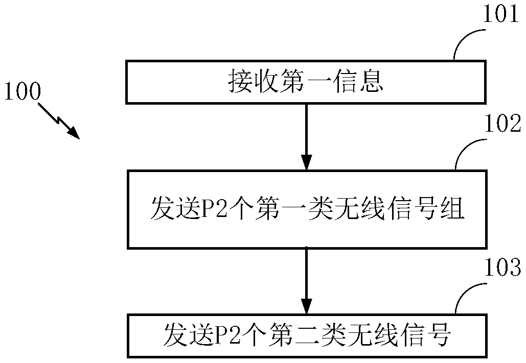
[0069] Embodiment 1 illustrates the first information according to an embodiment of the present application, the flow chart of the transmission of P2 first-type wireless signal groups and P2 second-type wireless signals, as shown in the attached figure 1 shown. attached figure 1 In , each box represents a step.

[0070] In Embodiment 1, the first type of communication node in this application first receives the first information; then sends P2 first type wireless signal groups; then sends P2 second wireless signals; wherein, the first information is used In order to determine the P2 first-type wireless signal groups, the P1 first-type wireless signals are divided into the P2 first-type wireless signal groups, and the P2 first-type wireless signal groups are related to the P2 first-type wireless signal groups. There is a one-to-one correspondence between the two types of wireless signals, the P2 is a positive integer greater than 1, and the P1 is a positive integer greater th...

Embodiment 2

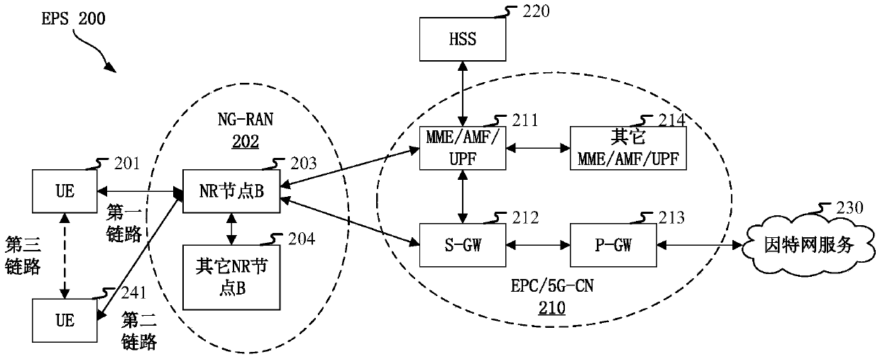
[0159] Embodiment 2 illustrates a schematic diagram of a network architecture according to the present application, as attached figure 2 shown. figure 2 It is a diagram illustrating NR 5G, LTE (Long-Term Evolution, long-term evolution) and LTE-A (Long-Term Evolution Advanced, enhanced long-term evolution) system network architecture 200. The NR 5G or LTE network architecture 200 may be referred to as an EPS (Evolved Packet System, Evolved Packet System) 200 . EPS 200 may include one or more UE (User Equipment, User Equipment) 201, NG-RAN (Next Generation Radio Access Network) 202, EPC (Evolved Packet Core, Evolved Packet Core) / 5G-CN (5G-Core Network , 5G core network) 210, HSS (Home Subscriber Server, home subscriber server) 220 and Internet service 230. The EPS may be interconnected with other access networks, but these entities / interfaces are not shown for simplicity. As shown, the EPS provides packet-switched services, however those skilled in the art will readily appr...

Embodiment 3

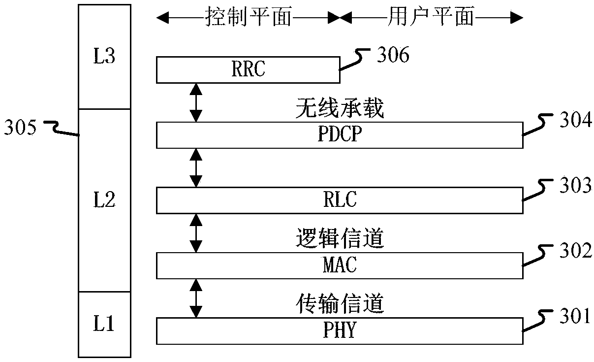
[0165] Embodiment 3 shows a schematic diagram of an embodiment of a wireless protocol architecture of a user plane and a control plane according to the present application, as shown in the attached image 3 shown. image 3 is a schematic diagram illustrating an embodiment of a radio protocol architecture for a user plane and a control plane, image 3 The radio protocol architecture for the first type of communication node device (UE) and the second type of communication node device (gNB, eNB or satellite or aircraft in NTN) is shown in three layers: layer 1, layer 2 and layer 3. Layer 1 (L1 layer) is the lowest layer and implements various PHY (Physical Layer) signal processing functions. The L1 layer will be referred to herein as PHY 301 . A layer 2 (L2 layer) 305 is above the PHY 301 and is responsible for a link between the first type of communication node device and the second type of communication node device through the PHY 301 . In the user plane, the L2 layer 305 in...


PUM


Abstract

The invention discloses a method and a device in a communication node for wireless communication. The communication node firstly receives the first information; then, P2 first type wireless signal groups are sent; then, P2 second type wireless signals are sent; the first information is used for determining P2 first type wireless signal groups, P1 first type wireless signals are divided into P2 first type wireless signal groups, and the P2 first type wireless signal groups are in one-to-one correspondence with P2 second type wireless signals; any one of the P2 second type wireless signals and the first type wireless signal in the first type wireless signal group corresponding to the P2 first type wireless signal group adopt the same space domain sending filter; the air interface resource occupied by any one of the P2 second type wireless signals is related to the air interface resource occupied by the first type wireless signal group corresponding to the P2 second type wireless signals.The resource utilization rate of non-granted transmission is improved.

Description

technical field [0001] The present application relates to a transmission method and device in a wireless communication system, in particular to an uplink non-granted transmission scheme and device. Background technique [0002] The application scenarios of future wireless communication systems are becoming more and more diversified, and different application scenarios put forward different performance requirements for the system. In order to meet the different performance requirements of various application scenarios, the new air interface technology (NR, New Radio) (or 5G) research, passed the WI (Work Item, work item) of the new air interface technology (NR, New Radio) at the 3GPP RAN#75 plenary meeting, and started to standardize NR. [0003] In order to be able to adapt to various application scenarios and meet different needs, the 3GPP RAN#76 plenary session also passed the research project of Non-orthogonal Multiple Access (NoMA, Non-orthogonal Multiple Access) under ...

Claims


Application Information

Patent Timeline
Patent Type & Authority Applications(China)
IPC IPC(8): H04W28/02H04W28/04H04W72/04H04W76/27
CPCH04W76/27H04W28/0205H04W28/04H04W72/046Y02D30/70
Inventor 刘铮张晓博
Owner SHANGHAI LANGBO COMM TECH CO LTD
Why Eureka
Try Eureka