
Bending equipment used for medical beauty equipment shell machining and provided with fixing structure

A fixed structure and equipment technology, applied in the direction of manufacturing tools, metal processing equipment, grinding/polishing equipment, etc., can solve the problems of inability to improve bending processing efficiency, inability to perform multi-function processing, inconvenient fast fixing, etc., to achieve Facilitate multiple processing, increase friction, and stabilize the clamping material

Inactive Publication Date: 2019-09-10
深圳市佳鑫一帆科技有限公司
View PDF16 Cites 0 Cited by
  • Summary
  • Abstract
  • Description
  • Claims
  • Application Information

AI Technical Summary

Problems solved by technology

[0003] A kind of bending equipment is disclosed in the Chinese invention patent application publication specification CN107597960A. Although the transmission component of the bending equipment can drive the bending parts to go back and forth along the second direction multiple times, it can improve the breaking efficiency of the product and reduce the driving force. The energy consumption of the device, prolonging the service life of the bending equipment, etc., but there are problems that it cannot perform multi-function processing, such as the inability to bend the material in different styles according to the processing needs of the material, and it is inconvenient and fast Fixed problem, and the device still has the problem of not being able to improve the processing efficiency after bending

Method used


Image

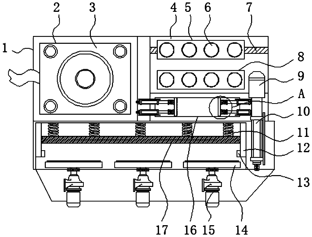
  • Bending equipment used for medical beauty equipment shell machining and provided with fixing structure
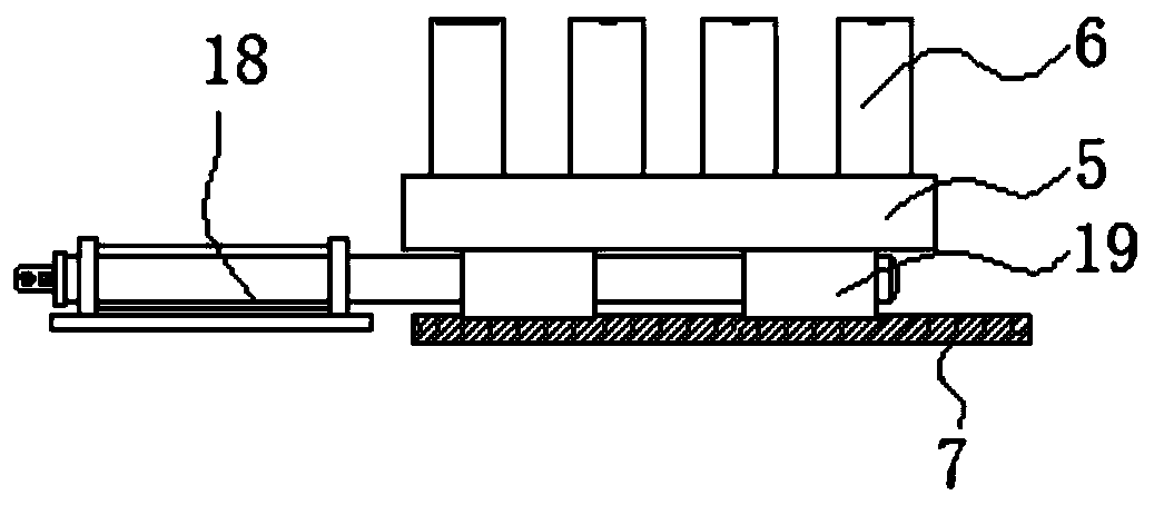
  • Bending equipment used for medical beauty equipment shell machining and provided with fixing structure
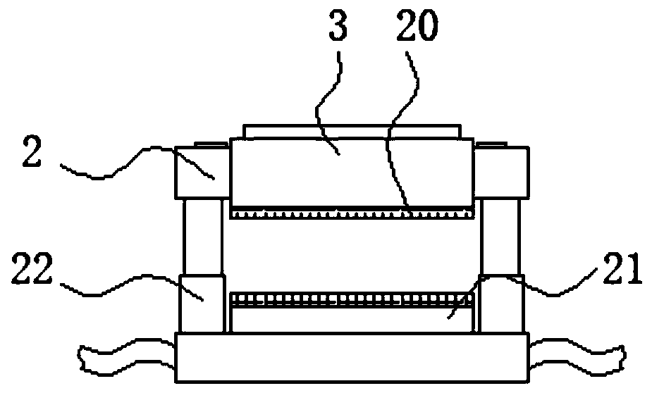
  • Bending equipment used for medical beauty equipment shell machining and provided with fixing structure

Examples


Embodiment Construction

[0026] The following will clearly and completely describe the technical solutions in the embodiments of the present invention with reference to the accompanying drawings in the embodiments of the present invention. Obviously, the described embodiments are only some, not all, embodiments of the present invention.

[0027] In the description of the present invention, unless otherwise stated, the meaning of "plurality" is two or more; the terms "upper", "lower", "left", "right", "inner", "outer" , "front end", "rear end", "head", "tail", etc. indicate the orientation or positional relationship based on the orientation or positional relationship shown in the drawings, and are only for the convenience of describing the present invention and simplifying the description, rather than Nothing indicating or implying that a referenced device or element must have a particular orientation, be constructed, and operate in a particular orientation should therefore not be construed as limiting ...


PUM


Abstract

The invention relates to bending equipment used for medical beauty equipment shell machining and provided with a fixing structure. The bending equipment comprises a main seat and a bending structure,an extrusion structure is installed at the upper end of the left side of the main seat, and a movable extrusion plate is installed at the top end of the extrusion structure. The bending equipment usedfor medical beauty equipment shell machining and provided with the fixing structure has the beneficial effects that by arranging fixing columns uniformly on bending plates, materials can be stuck ingaps between the fixing columns, the movable bending plate can move leftwards and rightwards in a slide cavity under action of a second hydraulic cylinder, thus, one ends of the stuck materials can bebent conveniently, meanwhile, the gap between the movable bending plate and the fixed bending plate can also clamp materials, a bending head is driven to ascend towards the front end by a first hydraulic cylinder, and accordingly, the top ends of the materials can be extruded and bent; and in this way, by setting multiple bending functions, different positions of materials can be bent as required, and operation is quite convenient.

Description

technical field [0001] The invention relates to the technical field of medical cosmetic equipment casing processing, in particular to a bending device with a fixed structure for processing a medical cosmetic equipment casing. Background technique [0002] With the development of the times, the development of the medical field is getting better and better, and there will be beauty equipment in the medical treatment, which is beneficial to the beauty equipment to assist in repairing or changing people's appearance, and to help people undergo treatment. In the production of medical beauty equipment shells , it is necessary to bend the material to facilitate the installation and assembly of equipment. [0003] A kind of bending equipment is disclosed in the Chinese invention patent application publication specification CN107597960A. Although the transmission component of the bending equipment can drive the bending parts to go back and forth along the second direction multiple ti...

Claims


Application Information

Patent Timeline
Patent Type & Authority Applications(China)
IPC IPC(8): B21D5/04B24B19/00B24B41/06B24B55/06
CPCB21D5/045B21D5/047B24B19/00B24B41/06B24B55/06
Inventor 段平泉邓美姣余洪业
Owner 深圳市佳鑫一帆科技有限公司
Learn More