Gear transmission structure

A gear transmission and gear technology, which is applied to transmission parts, gear lubrication/cooling, belt/chain/gear, etc., can solve the problems of cost increase, gear damage, and low gear life

Pending Publication Date: 2019-09-10
GUANGDONG POLYTECHNIC NORMAL UNIV
View PDF0 Cites 6 Cited by
  • Summary
  • Abstract
  • Description
  • Claims
  • Application Information

AI Technical Summary

Problems solved by technology

However, the gears are prone to damage to varying degrees under certain heavy loads and poor lubrication conditions, which eventually makes the gears fail
At present, during the lubrication process, there will be a problem of uneven lubricating oil quantity at...

Method used


Image

  • Gear transmission structure
  • Gear transmission structure
  • Gear transmission structure

Examples


Embodiment 1

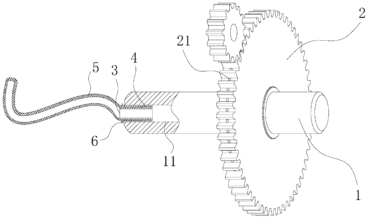
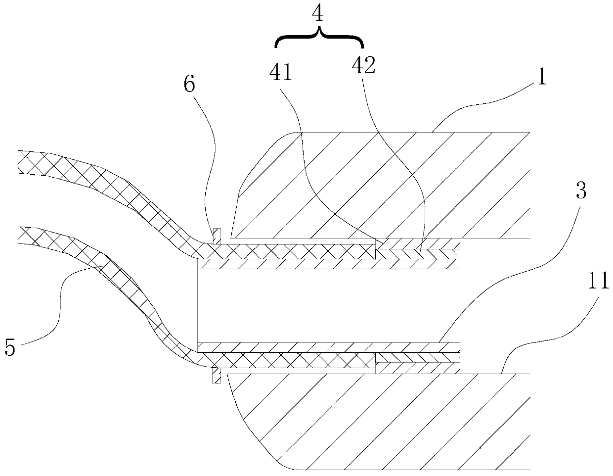
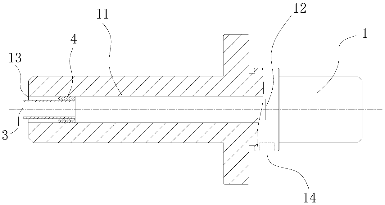
[0025] Please refer to Figure 1-Figure 3 , Embodiment 1 provides a gear transmission structure, including a rotating shaft 1 and a gear 2, the rotating shaft 1 has an oil inlet passage 11 and an oil passage groove 12, the oil inlet passage 11 is arranged inside the rotating shaft 1, and the oil passage groove 12 is arranged in The outer wall of the shaft 1, and the oil groove 12 communicates with the oil inlet passage 11, and the gear 2 has an oil hole 21 inside, and the first end of the oil hole 21 is set on the tooth of the gear 2 or where the root circle of the gear 2 is. The second end of the oil hole 21 is set on the inner wall of the center hole, the gear 2 is sleeved on the rotating shaft 1 and the oil hole 21 communicates with the oil groove 12 . When supplying oil to the oil inlet passage 11, lubricating oil enters the oil inlet passage 11, flows into the oil passage groove 12 from the oil inlet passage 11, and then flows through the oil passage groove 12 through the...

Embodiment 2

[0030] The gear transmission structure provided by the second embodiment differs from the first embodiment in that the cross-sectional area of ​​the first end of the oil through hole 21 is smaller than the cross-sectional area of ​​the second end of the oil through hole 21 . Embodiment 2 is suitable for occasions with heavy loads, and the effect of the hydrodynamic oil film formed at the meshing position of the gears 2 under this working condition is better than that of Embodiment 1.

[0031] The above is the preferred embodiment of the present invention. In the preferred embodiment of the present invention, an oil passage 21 is provided inside the gear 2, and an oil inlet channel 11 and an oil passage 12 are provided in the rotating shaft 1 to deliver the lubricating oil to the meshing part of the gear 2. , so that the gear 2 forms a hydrodynamic oil film at the meshing point to ensure the lubricating effect, and at the same time, the amount of lubricating oil is uniform, the ...


PUM


Abstract

The invention provides a gear transmission structure comprising a rotating shaft and a gear. The rotating shaft is provided with an oil inlet channel and an oil communication groove. The oil inlet channel is arranged inside the rotating shaft. The oil communication groove is arranged on the outer wall of the rotating shaft and communicates with the oil inlet channel. Oil communication holes are formed inside the gear. The first end of each oil communication hole is arranged on a gear tooth of the gear or the surface where a root circle of the gear is located. The second end of each oil communication hole is arranged on the inner wall of the center hole. The gear is arranged on the rotating shaft in a sleeving manner, and the oil communication hole communicates with the oil communication groove. According to the gear transmission structure, lubricating oil is conveyed to the engagement position of the gear, so that the gear forms liquid dynamic pressure oil film at the engagement position, and the lubricating effect is guaranteed; it is guaranteed that the lubricating oil amount is uniform, the lubricating effect is uniform, and the lubricating oil is saved.

Description

technical field [0001] The invention relates to a gear transmission structure. Background technique [0002] The current gear transmission structure is widely used in many fields, such as in automobiles, ships, airplanes, and currently popular robots and other equipment, and the transmission efficiency is high. However, gears are prone to damage to varying degrees under certain heavy loads and poor lubrication conditions, which eventually makes the gears fail. At present, the problem of uneven amount of lubricating oil at the gear meshes occurs during the lubrication process. When the amount of lubricating oil is small, the lubricating effect will be poor and the life of the gears will be short; and when the amount of lubricating oil is large, the lubricating oil will be wasted, resulting in increased costs. Contents of the invention [0003] In order to solve the above-mentioned technical problems, the object of the present invention is to provide a gear transmission st...

Claims


Application Information

Patent Timeline
IPC IPC(8): F16H57/04
CPCF16H57/043F16H57/0431
Inventor 徐兰英毛世杰伍强何宝兰赵鹏
Owner GUANGDONG POLYTECHNIC NORMAL UNIV
Why Eureka
Try Eureka