
Borehole inner wall ultrasonic scanning and imaging device and method

A scanning imaging and ultrasonic technology, which is applied in the direction of using ultrasonic/sonic/infrasonic waves, measuring devices, instruments, etc., can solve the problem of unclear gradient process of drilling holes, inaccurate judgment of hole position, and inaccurate hole collapse severity. Clear and other problems to achieve good imaging results, improve stability and accuracy, and use simple methods

Active Publication Date: 2019-09-10
XIAN UNIV OF SCI & TECH
View PDF5 Cites 1 Cited by
  • Summary
  • Abstract
  • Description
  • Claims
  • Application Information

AI Technical Summary

Problems solved by technology

Therefore, the judgment of the location of the collapsed hole and the mastery of the layout of the entire length of the hole wall are important foundations for the prevention and control of the entire hole collapse. The traditional method of judging the location of the collapsed hole mostly relies on the amount of cuttings during the drilling process combined with the work experience of the worker's master. Make a rough judgment, the judgment accuracy is not high, the severity of the hole collapse is not clear, and the situation of the entire hole wall after the hole is drilled cannot be effectively grasped
There are problems such as inaccurate judgment of the position of the collapsed hole and unclear gradual change process of the hole circumference of the drilled hole

Method used


Image

  • Borehole inner wall ultrasonic scanning and imaging device and method
  • Borehole inner wall ultrasonic scanning and imaging device and method
  • Borehole inner wall ultrasonic scanning and imaging device and method

Examples


Embodiment Construction

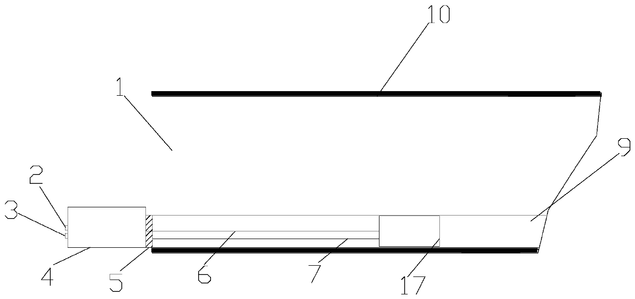
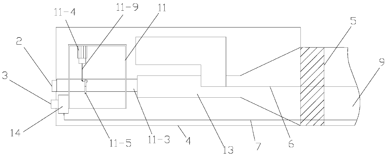
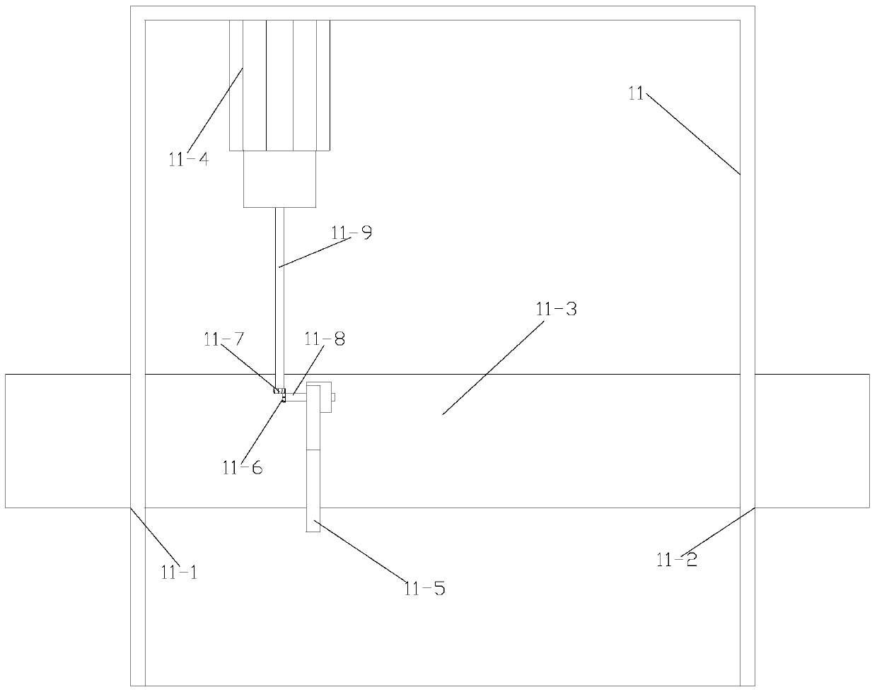
[0056] Such as Figure 1 to Figure 8 As shown, the ultrasonic scanning imaging device for the inner wall of the borehole of the present invention includes an external connection unit 4, a guide tube body 9 and a scanning unit arranged inside the guide tube body 9, and the scanning unit is slidably arranged inside the guide tube body 9;

[0057] The external unit 4 includes a numerical control module connected to the computer 22 and a wind speed control device connected to the external air duct 2; the numerical control module is connected to the scanning unit, and the wind speed control device is provided with a Air cylinder 13, described air cylinder 13 communicates with wind speed control device, described air cylinder 13 and one end far away from wind speed control device is connected with guide pipe body 9; Between described numerical control module and scanning unit, be provided with for connecting numerical control module and The magnetic pull wire 6 of the scanning unit;...


PUM


Abstract

The invention provides a borehole inner wall ultrasonic scanning and imaging device, which comprises an external connection unit, a guidance pipe body and a scanning unit, wherein the external connection unit comprises a numerical control module and a wind speed regulation and control device; the numerical control module is connected with the scanning unit; the wind speed regulation and control device is provided with an air duct which is independently connected with the wind speed regulation and control device and the guidance pipe body; a magnetic pull wire is arranged between the numericalcontrol module and the scanning unit; the scanning unit comprises a scanning unit shell, wherein an ultrasonic distance measuring instrument and a scanning driving motor are arranged in the scanning unit shell; the motor shaft of the scanning driving motor is connected with a transmission shaft; the transmission shaft is connected with the ultrasonic distance measuring instrument; and the ultrasonic distance measuring instrument is provided with an ultrasonic probe. In addition, the invention also provides a scanning and imaging method for the above borehole inner wall ultrasonic scanning andimaging device. By use of the device disclosed by the invention, the three-image scanning and imaging of the borehole inner wall can be realized, a three-dimensional scanning image of a whole boreholeis obtained, and the detection of a hole collapsing position of the borehole is realized.

Description

technical field [0001] The invention belongs to the technical field of coal mining, and in particular relates to an ultrasonic scanning imaging device and method for the inner wall of a borehole. Background technique [0002] Coal mining conditions in most areas of the country are harsh, the mining depth is large, the gas content in the coal seam is high, the pressure is high, the gas permeability of the coal seam is low, the geological structure conditions are complex, and gas accidents are prone to occur. Reducing and preventing gas accidents has become an urgent problem in the field of coal mine safety. The problem. At present, the most common method of gas drainage in my country is to use boreholes to pre-drain the coal seam gas in the mining face. The most commonly used method of gas drainage is comprehensive gas drainage. Ground vertical-downhole horizontal directional drilling and underground coal seam drilling. Because the coal body becomes soft in the high-gassy so...

Claims


Application Information

Patent Timeline
IPC IPC(8): G01B17/06G01B17/00
CPCG01B17/06G01B17/00
Inventor 张超刘超靳高汉杨朴超王星龙薛俊华孙宝强常杰刘华
Owner XIAN UNIV OF SCI & TECH
Learn More