Circumference security radar system

A radar system and anti-radar technology, used in radio wave measurement systems, radio wave reflection/re-radiation, and use of re-radiation, etc. and other problems, to achieve the effect of improving sensitivity and accuracy, and avoiding detection dead ends.

Pending Publication Date: 2019-09-10
西安象德信息技术有限公司
0 Cites 1 Cited by

AI-Extracted Technical Summary

Problems solved by technology

The problem with microwave cross-firing is that it is impossible to locate targets with radial movement speed. When the...

Method used

In like manner, in some embodiments, at least one 3rd radar assembly 30 comprises a plurality of 3rd radar assemblies, the second microwave transmitting unit of each described 3rd radar assembly is provided with the second polarization of different polarization directions film, the corresponding second microwave receiving unit is provided with the same second polarizing film as its paired second microwave transmitting unit. The principle of the multi-angle arrangement of the third radar assembly 30 is similar to that of the second radar assembly 20 , so details are not repeated here. Through the third radar assembly 30 arranged at multiple angles, it is convenient to detect people crossing the boundary in various moving directions, and the sensitivity and accuracy of detection can be improved. One of the plurality of third radar assemblies is arranged along an extending direction perpendicular to the perimeter to be monitored, and other third radar assemblies of the plurality of third radar assemblies are arranged obliquely.
[0036] As shown in FIG. 2, in this figure, the first radar assembly and the third radar assembly are not shown. In some embodiments, at least one second radar as...

Abstract

The invention discloses a circumference security radar system. The system comprises a first radar module, at least one second radar module, at least one third radar module, multiple infrared detectionsensors and master control equipment; the first radar module comprises a first signal emission unit, a first signal receiving unit and a signal reflector; the first signal emission unit and the firstsignal receiving unit and the radar reflector are arranged at two ends of to-be-monitored circumference, wherein the first signal emission unit and the first signal receiving unit are located at thesame end, and the radar reflector is located at the other opposite end; the first signal emission unit emits first microwave energy to the to-be-monitored circumference, the first microwave energy isreflected to the first signal receiving unit through the signal reflector, the first signal receiving unit judges whether the circumference through behavior is existent by monitoring the first microwave energy; and the second radar module comprises a first microwave emission unit and a first microwave receiving unit. Through the circumference security radar system provided by the invention, the sensitivity and accuracy of the detection can be improved, and the dead angle detection is avoided.

Application Domain

Radio wave reradiation/reflection

Technology Topic

Signal reflectionControl equipment +3

Image

  • Circumference security radar system
  • Circumference security radar system

Examples

  • Experimental program(1)

Example Embodiment

[0022] The present invention will be described in detail below with reference to the drawings and specific embodiments.
[0023] The following describes the embodiments of the present invention in detail. Examples of the embodiments are shown in the accompanying drawings, wherein the same or similar reference numerals indicate the same or similar elements or elements with the same or similar functions. The following embodiments described with reference to the accompanying drawings are exemplary, and are only used to explain the present invention, and cannot be understood as a limitation to the present invention.
[0024] In the description of the present invention, it should be understood that the terms "center", "longitudinal", "transverse", "length", "width", "thickness", "upper", "lower", "front", " "Back", "Left", "Right", "Vertical", "Horizontal", "Top", "Bottom", "Inner", "Outer", "Clockwise", "Counterclockwise" and other directions or The positional relationship is based on the position or positional relationship shown in the drawings, and is only for the convenience of describing the present invention and simplifying the description, and does not indicate or imply that the pointed device or element must have a specific orientation, be constructed and operated in a specific orientation, Therefore, it cannot be understood as a limitation to the present invention. In addition, the terms "first" and "second" are only used for descriptive purposes, and cannot be understood as indicating or implying relative importance or implicitly indicating the number of indicated technical features. Therefore, the features defined with "first" and "second" may explicitly or implicitly include one or more of the features. In the description of the present invention, "plurality" means two or more than two, unless specifically defined otherwise.
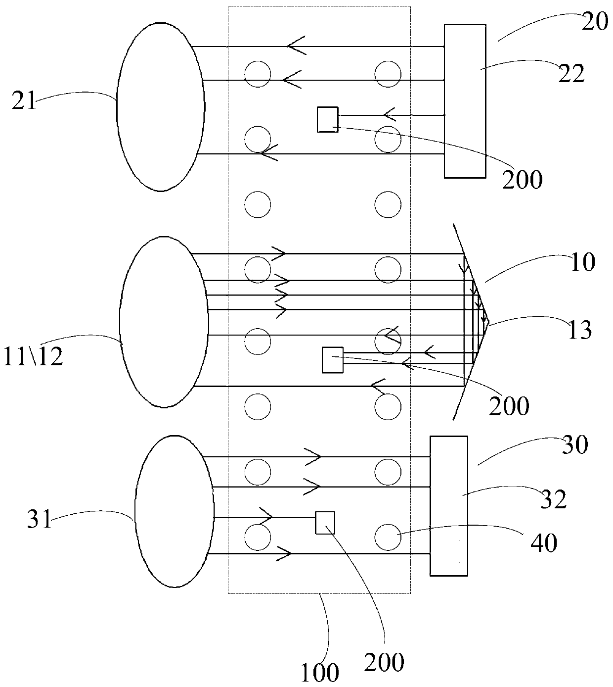
[0025] Please refer to figure 1 , figure 1 It is a schematic diagram of the perimeter security radar system in some embodiments of the present invention.
[0026] In this embodiment, the perimeter security radar system includes a first radar component 10, a second radar component 20, a third radar component 30, a plurality of infrared detection sensors 40, and a main control device (not shown). The first radar component 10 and the other second radar components 20 and a third radar component 30 are in different frequency bands.
[0027] Wherein, the first radar component 10 includes a first signal transmitting unit 11, a first signal receiving unit 12 and a signal reflector 13. Wherein, the first signal transmitting unit 11 and the first signal receiving unit 12 and the radar reflector 13 are respectively arranged at two ends of the perimeter 100 to be monitored. The first signal transmitting unit 11 and the first signal receiving unit 12 are located at the same end. The first signal transmitting unit 11 transmits first microwave energy to the perimeter to be monitored 100. The first microwave energy is reflected by the signal reflector 13 to the first signal receiving unit 12, and the first signal receiving unit 12 A monitoring of the magnitude of microwave energy to determine whether there is perimeter crossing behavior.
[0028] Wherein, the second radar assembly 20 includes a first microwave transmitting unit 21 and a first microwave receiving unit 22. The first microwave transmitting unit 21 and the first microwave receiving unit 22 are respectively arranged at both ends of the perimeter 100 to be monitored. . The first microwave transmitting unit 21 and the first microwave receiving unit 22 of the second radar assembly 20 realize synchronous operation through the main control device, for example, IEEE1588 synchronous Ethernet can be used to connect to the main control device.
[0029] Wherein, the third radar assembly 30 includes a second microwave transmitting unit 32 and a second microwave receiving unit 31. The second microwave transmitting unit 32 and the second microwave receiving unit 31 are respectively arranged at both ends of the perimeter 100 to be monitored, and The first microwave transmitting unit 21 and the second microwave receiving unit 31 are located at the same end, and the first microwave receiving unit 22 and the second microwave transmitting unit 32 are located at the same end.
[0030] The second microwave transmitting unit 32 and the second microwave receiving unit 31 realize synchronous operation through a synchronization system, for example, IEEE1588 synchronous Ethernet can be used to connect to the main control device.
[0031] The second microwave transmitting unit 32 and the first microwave transmitting unit 21 are both composed of an antenna and a microwave generating circuit. The second microwave transmitting unit 32 radiates the third microwave energy, and the second microwave receiving unit 31 will receive the third microwave energy, and by monitoring the magnitude of the third microwave energy, it is determined whether there is a perimeter crossing behavior.
[0032] Wherein, the main control device is respectively communicatively connected with the first radar component 10, the second radar component 20, the third radar component 30, and a plurality of infrared detection sensors 40, and the plurality of infrared detection sensors are evenly spaced along the boundary. distributed. When the infrared detection sensor detects the heat source, the main control device controls the first radar assembly 10, the second radar assembly 20, and the third radar assembly 30 to simultaneously power on. When it is not detected, the first radar assembly 10, the second radar assembly The radar component 20 and the third radar component 30 are alternately powered on at preset time intervals.
[0033] In some embodiments, the signal reflector 13 is a passive reflector or an active radar beacon.
[0034] In some embodiments, the signal reflector 13 is a cross-polarization reflector, and the first radar component 10 has a cross-polarization characteristic.
[0035] In some embodiments, the signal reflector 13 is an active beacon, and the first radar component 10 and the signal reflector 13 are synchronized to work through a synchronization system.
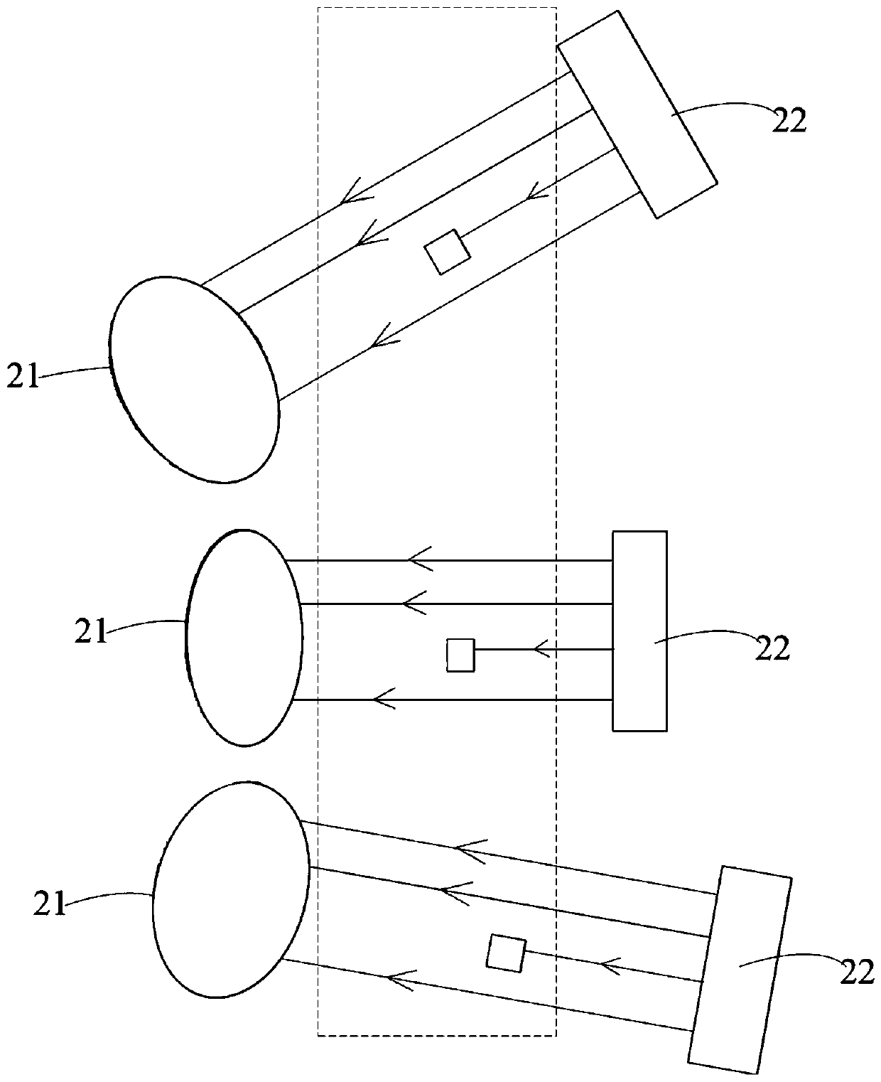
[0036] Such as figure 2 As shown, in this figure, the first radar component and the third radar component are not shown. In some embodiments, at least one second radar component 20 includes a plurality of second radar components 20, and the first signal transmitting unit of each second radar component 20 is provided with first polarizing films with different polarization directions, corresponding to The first microwave receiving unit is provided with a first polarizing film that is the same as the first microwave emitting unit that is paired with it. The plurality of second radar components are arranged along different angles. The second radar component 20 arranged at multiple angles facilitates the detection of cross-border persons in various moving directions, and can improve the sensitivity and accuracy of detection. One second radar component of the plurality of second radar components is arranged along an extension direction perpendicular to the perimeter to be monitored, and the other third radar components of the plurality of second radar components are arranged obliquely.
[0037] Similarly, in some embodiments, at least one third radar component 30 includes a plurality of third radar components, and the second microwave transmitting unit of each third radar component is provided with second polarizing films with different polarization directions, corresponding to The second microwave receiving unit is provided with a second polarizing film that is the same as the second microwave emitting unit that is paired with. The multi-angle setting of the third radar component 30 is similar to the principle of the multi-angle setting of the second radar component 20, so it will not be repeated. The third radar assembly 30 arranged at multiple angles facilitates the detection of cross-border persons in various moving directions, and can improve the sensitivity and accuracy of detection. One third radar component of the plurality of third radar components is arranged along an extension direction perpendicular to the perimeter to be monitored, and the other third radar components of the plurality of third radar components are arranged obliquely.
[0038] In the above manner, the perimeter security radar system provided by the present invention can detect cross-border persons in various directions through the cooperation of multiple radar detection methods, can improve the sensitivity and accuracy of detection, and avoid detecting dead ends.
[0039] In the description of this specification, the description with reference to the terms "one embodiment", "certain embodiments", "exemplary embodiments", "examples", "specific examples", or "some examples", etc. means to combine The specific features, structures, materials or characteristics described in the embodiments or examples are included in at least one embodiment or example of the present invention. In this specification, the schematic representation of the above-mentioned terms does not necessarily refer to the same embodiment or example. Moreover, the described specific features, structures, materials or characteristics can be combined in an appropriate manner in any one or more embodiments or examples.
[0040] In summary, although the present invention has been disclosed in preferred embodiments as above, the above-mentioned preferred embodiments are not intended to limit the present invention. Those of ordinary skill in the art can make various modifications without departing from the spirit and scope of the present invention. Such changes and modifications, therefore, the protection scope of the present invention is subject to the scope defined by the claims.

PUM

no PUM

Description & Claims & Application Information

We can also present the details of the Description, Claims and Application information to help users get a comprehensive understanding of the technical details of the patent, such as background art, summary of invention, brief description of drawings, description of embodiments, and other original content. On the other hand, users can also determine the specific scope of protection of the technology through the list of claims; as well as understand the changes in the life cycle of the technology with the presentation of the patent timeline. Login to view more.

Similar technology patents

Pneumatic-based tactile sensor

ActiveUS20200041361A1prevent hysteresis phenomenonimprove sensitivity and accuracy
Owner:KOREA INST OF MASCH & MATERIALS

Classification and recommendation of technical efficacy words

  • Improve sensitivity and accuracy
  • Avoid detecting blind spots

Method for measuring focal plane uniformity of exposure machine

ActiveCN101650534AOvercome the monotony of graphicsImprove sensitivity and accuracy
Owner:SHANGHAI HUAHONG GRACE SEMICON MFG CORP

Electrical equipment partial discharge detection device

PendingCN113358989AImprove the detection effectAvoid detecting blind spots
Owner:SHANGHAI XIBANG ELECTRIC
Why Eureka
Try Eureka