
Speed control of any override range effective over a plurality of blocks

A speed control and speed technology, applied in the direction of digital control, electrical program control, etc., can solve the problems of the utilization limit of the electric drive device, the limit of the beyond range, etc., to achieve the effect of expanding applicability, improving flexibility, and reliable work

Inactive Publication Date: 2003-02-26
SIEMENS AG
View PDF0 Cites 0 Cited by
  • Summary
  • Abstract
  • Description
  • Claims
  • Application Information

AI Technical Summary

Problems solved by technology

Therefore, on the one hand, it is not possible to foresee braking for several arrays, or on the other hand, the overreach of the effective coverage is extremely limited.
The disadvantage of these two methods of standard application is therefore that the utilization of the efficiency of the electric drive is usually limited

Method used


Image

  • Speed control of any override range effective over a plurality of blocks
  • Speed control of any override range effective over a plurality of blocks
  • Speed control of any override range effective over a plurality of blocks

Examples


Embodiment Construction

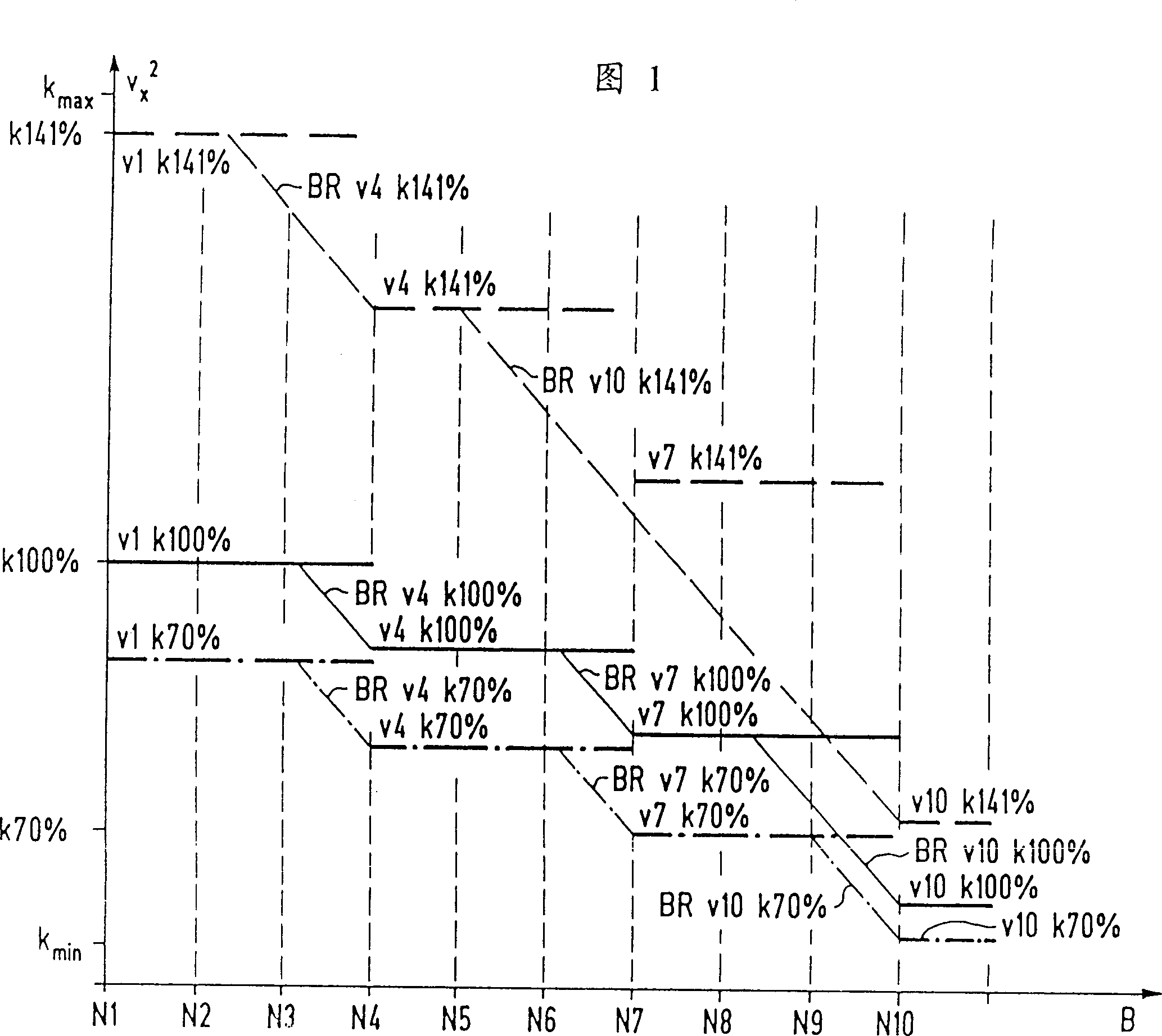
[0030] A curve is shown in Fig. 1, which illustrates the programming speed process of ten control arrays that are used for various adjustments beyond the range. On the abscissa are the control arrays N1...N10 on the trajectory length B. The coordinate represents the speed change, and the X-dimensional mechanical axis is exemplarily selected from other adopted mechanical axes. For the sake of readability, the braking distance can be expressed linearly, so the speed change V 2 x , Expressed by square. The speed change is shown as a curve K100% in the form of a curve K100% in the form of a profile view of the programmed rated speed exceeding the value of 100%. The speed curve K141% shows the same change over 141% in the form of a dashed curve. K70% shows a third speed curve with less overtaking, which is exemplarily the same as over 70% here, and is shown by a dash-dotted line. Exemplarily control the speed without being affected by the overriding value of a certain observation, so ...


PUM


Abstract

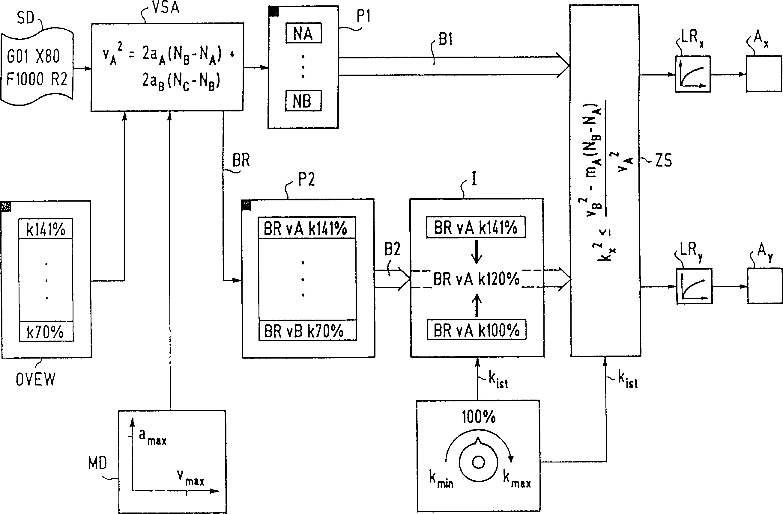
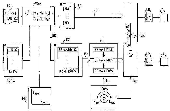
The invention relates to a prospective speed control for electric drives encompasses a plurality of blocks. The braking force required in several subsequent control data blocks (SD) to reliably slow the feedrate down to the programmed feedrate is prospectively analysed by reproducing limiting conditions (MD) such as admissible track acceleration (amax) and block length on the required braking path (BR), so that the thus determined shortest braking ramp (BR) represents the limiting condition. The braking ramps (BR) for several parametrable override transition values (OVEW) are associated as characteristic data with each analysed control data block (SD) in a data storage (P2) and are interpolated between the determined characteristic data (BR) in an interpolator (I) according to an actual predetermined override value (Kist) in order to derive therefrom the end-of-block speed required to avoid an excessive feedrate in the subsequent block.

Description

Technical field [0001] The invention relates to a speed control method and a device for predicting an electric drive device and overlapping an array. Background technique [0002] In modern industrial control such as machine tools or robots, the advancement for speed control is generally pre-set in the form of subroutine arrays. In order to reliably proceed with advances that are not faster than programming, the current advances must be reduced in time. This is because, for example, when array supplement interference occurs, the following situation will occur: because the current propulsion speed is very high, there is not enough time for the electric drive device to reach a stationary state from the high propulsion speed within the required time. When the programming advancement of the subsequent control array of the subroutine is much lower than the instantaneous current running advancing speed, due to the limited acceleration possibility of the electric ...

Claims


Application Information

Patent Timeline
IPC IPC(8): G05B19/416
CPCG05B19/416
Inventor 于尔根·米勒沃尔夫冈·斯佩思威廉·韦斯特迈耶
Owner SIEMENS AG
Learn More