
Multi-damping-layer local area resonon unit and application method thereof

A local resonance and damping layer technology, applied in the field of multi-damping layer local resonance sub-units, can solve the problems of large noise, complexity, and difficulty in implementation, and achieve effective vibration reduction frequency domain increase, good vibration reduction, noise reduction, and vibration Effect of Noise Reduction

Pending Publication Date: 2019-09-13
苏州英磁新能源科技有限公司
View PDF0 Cites 6 Cited by
  • Summary
  • Abstract
  • Description
  • Claims
  • Application Information

AI Technical Summary

Problems solved by technology

This type of method can only optimize the vibration and noise of the motor at the design end, but since the structure of the permanent magnet synchronous motor for new energy vehicles usually needs to be designed to match the power system of the vehicle, its mechanical structure, especially the casing, usually has a relatively complex structure , the mechanical connection of different placement points is relatively complicated, so the vibration of the motor cannot be fully considered at the design end
Therefore, the optimization scheme at the design end is complete, but it is difficult to avoid the phenomenon of excessive noise during the loading test of the manufactured prototype, and the traditional method of setting different damping absorbers is largely affected by the quality and structural size of the vehicle design. The strict requirements of the restrictions, while difficult to implement

Method used


Image

  • Multi-damping-layer local area resonon unit and application method thereof
  • Multi-damping-layer local area resonon unit and application method thereof
  • Multi-damping-layer local area resonon unit and application method thereof

Examples


Embodiment Construction

[0034] The technical solutions of the present invention will be clearly and completely described below in conjunction with the accompanying drawings. Apparently, the described embodiments are some of the embodiments of the present invention, but not all of them. Based on the embodiments of the present invention, all other embodiments obtained by persons of ordinary skill in the art without making creative efforts belong to the protection scope of the present invention.

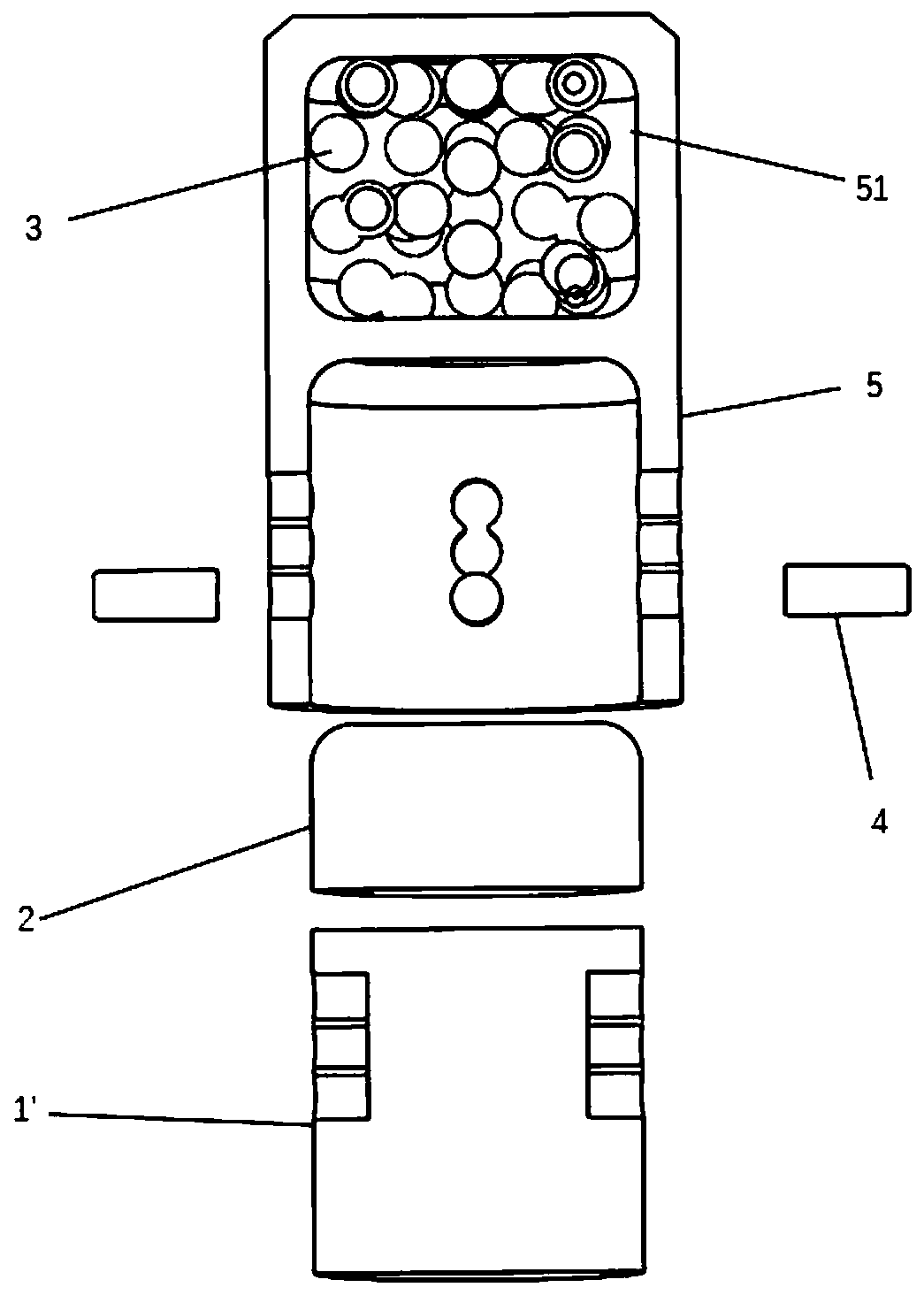
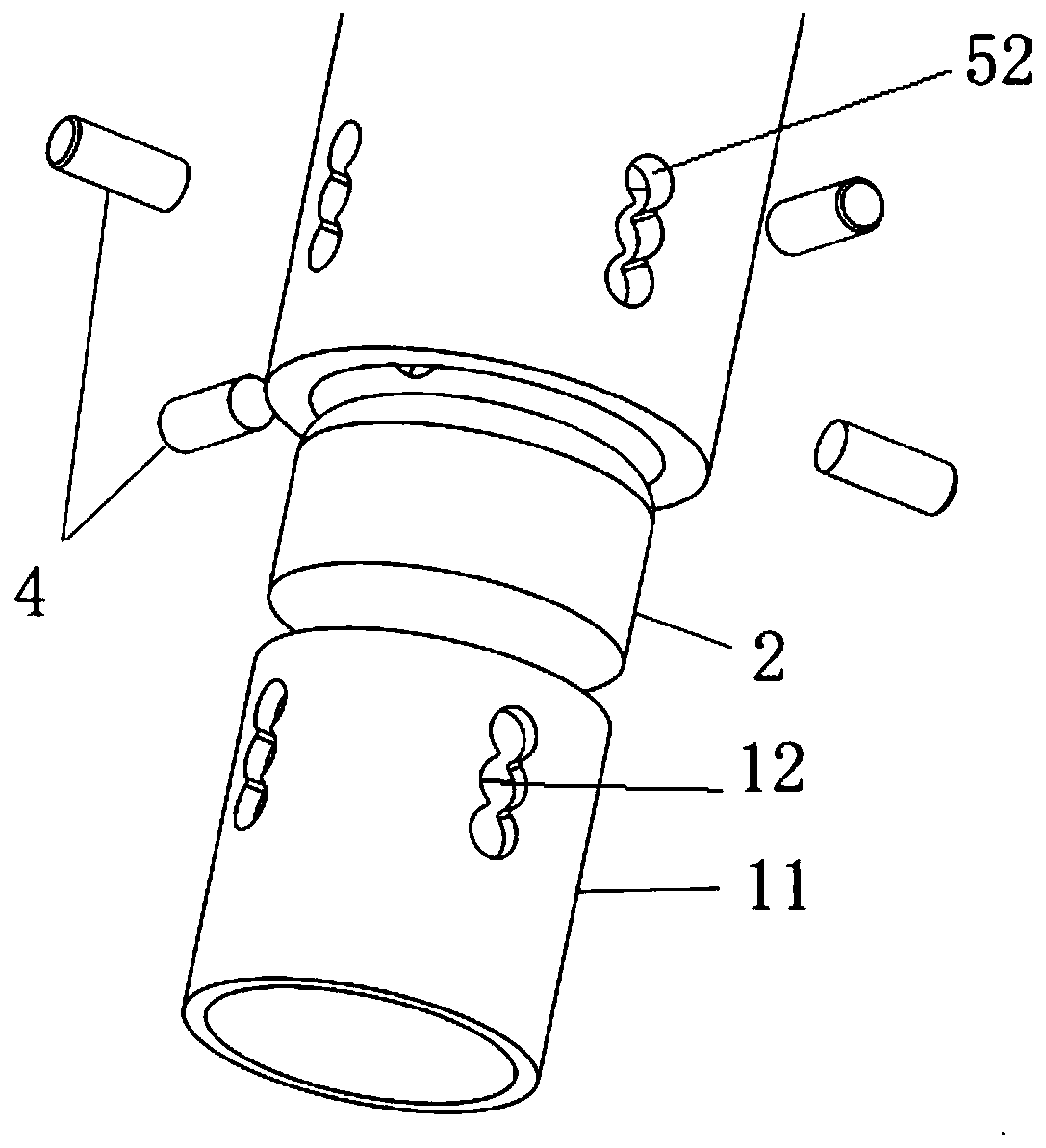
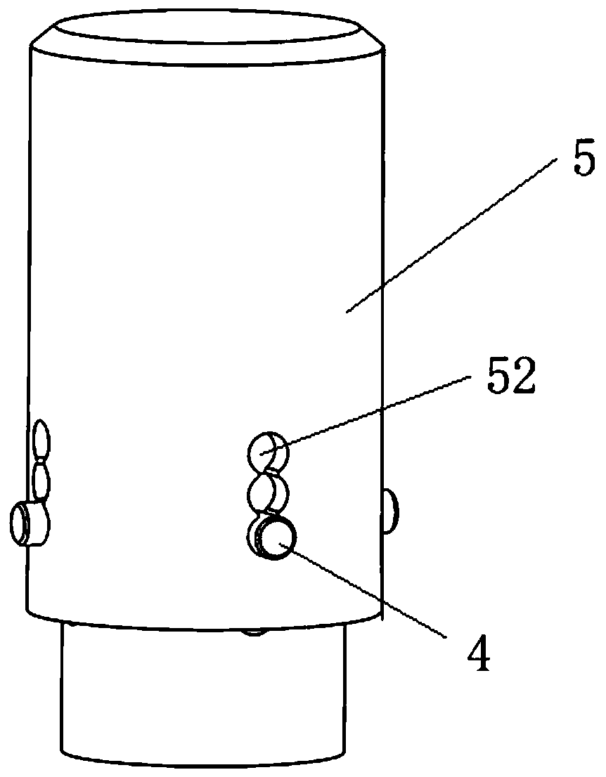
[0035] The present invention provides a local resonant sub-unit with multiple damping layers. For details, see figure 1 , comprising a rigid shell 5, which differs from the prior art in that: an inner spacer is provided in the middle of the rigid shell to divide the inner cavity of the rigid shell into upper and lower layers, and the upper space is provided with a third powder damping layer 3. The third powder damping layer is provided with a powder 31, which accounts for 65-75% of the volume of the entire upp...


PUM

PropertyMeasurementUnit
diameteraaaaaaaaaa
diameteraaaaaaaaaa
dielectric loss factoraaaaaaaaaa

Abstract

The invention relates to a multi-damping-layer local area resonon unit. An inner spacing ring is arranged in a rigid outer shell for dividing an inner cavity of the rigid outer shell into upper and lower layers; a third powder damping layer is arranged in the upper-layer space, and is provided with powder particle bodies; the powder particle bodies are 65-75% of the total volume of the upper-layerspace; the lower-layer space is provided with a second viscous-elastic material damping layer and a first vibration layer in sequence from top to bottom; and the bottom of the first vibration layer is projected on the bottom edge of the rigid outer shell. Through structures of damping layers with three different materials, the prominent effects of the three damping layers on a medium-frequency area and a high-frequency area are complementary, so that the excellent damping and noise reducing effects are achieved; and multiple multi-damping-layer local area resonon units form lattices in use touniformly distribute on the outer surface of the shell, so that the effective vibration reducing frequency domain is greatly widened, and the obvious weakening effect on 200-4000 Hz vibration noise generated by a motor is achieved.

Description

technical field [0001] The invention relates to the technical field of vibration reduction and noise reduction of permanent magnet synchronous motors, in particular to a multi-damping layer local resonant sub-unit for vibration reduction and noise reduction of a motor casing of a new energy vehicle, in particular to an acoustic The periodic arrangement of metamaterials and different damping energy-absorbing structures absorb and dissipate the vibration energy generated by the motor to achieve the purpose of vibration reduction and noise reduction. The multi-damping layer local resonance subunit. Background technique [0002] This year, new energy passenger vehicles driven by pure electric vehicles have become the mainstream development direction of the automobile industry, and permanent magnet synchronous motors are also more widely used in the design of passenger vehicle drive systems due to their advantages such as light weight and high power density. middle. With the hig...

Claims


Application Information

Patent Timeline
Patent Type & Authority Applications(China)
IPC IPC(8): F16F13/04F16F13/00F16F7/01F16F7/10H02K5/24
CPCF16F13/04F16F13/00F16F7/015F16F7/1034H02K5/24F16F2224/025F16F2224/02F16F2222/04F16F2222/08F16F2224/0208F16F2230/0041F16F2228/06
Inventor 裴瑞琳高凌宇
Owner 苏州英磁新能源科技有限公司
Learn More