
An electric steering gear system

A technology of electric steering gear and steering gear, which is applied in the direction of motor vehicle, aircraft transmission, aircraft power transmission, etc., can solve the problem that the electric steering gear cannot meet the requirements

Active Publication Date: 2021-06-11
XIAN AEROSPACE PRECISION ELECTROMECHANICAL INST
View PDF0 Cites 0 Cited by
  • Summary
  • Abstract
  • Description
  • Claims
  • Application Information

AI Technical Summary

Problems solved by technology

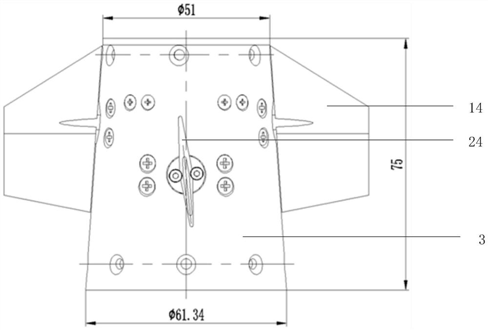
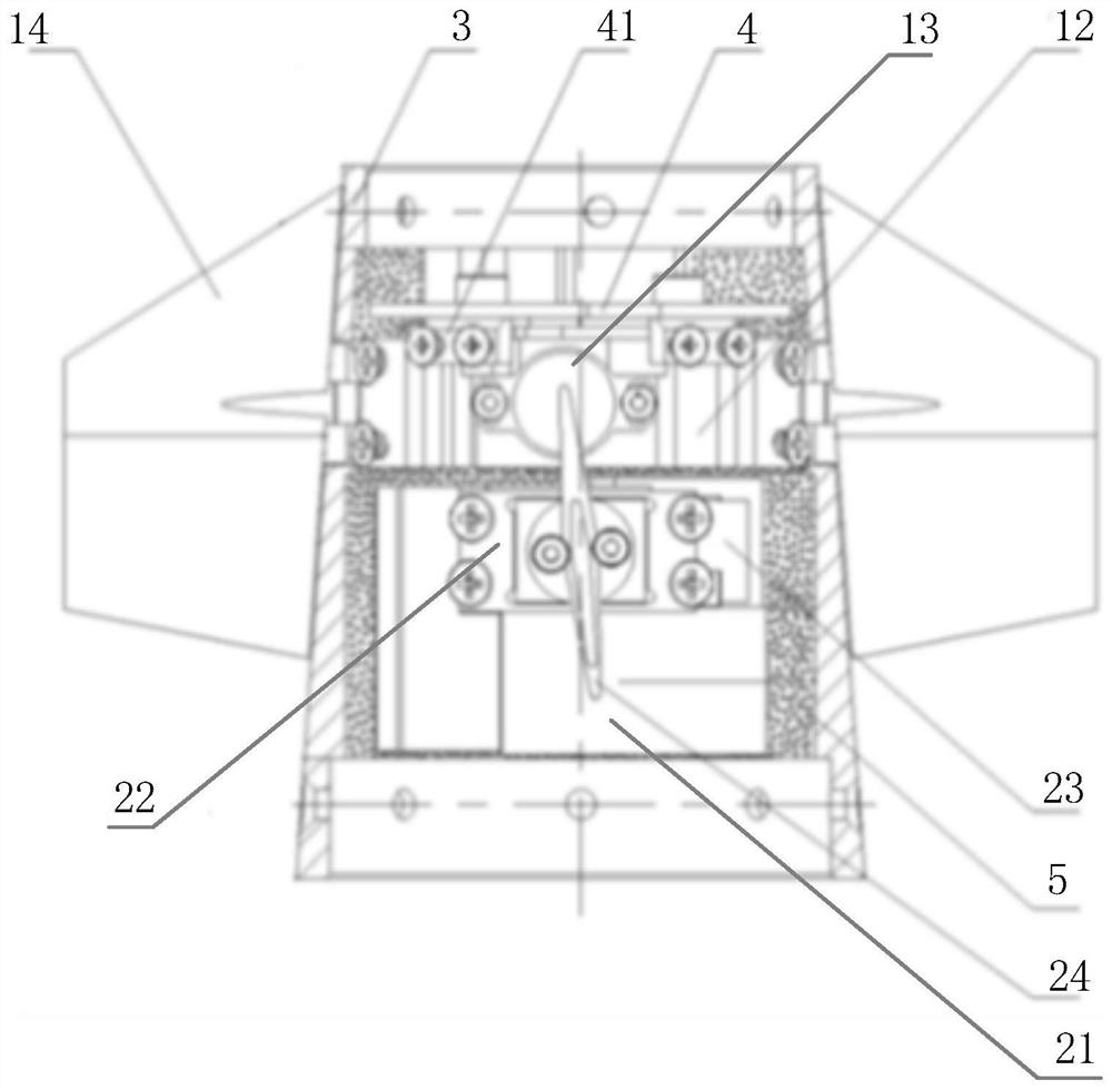
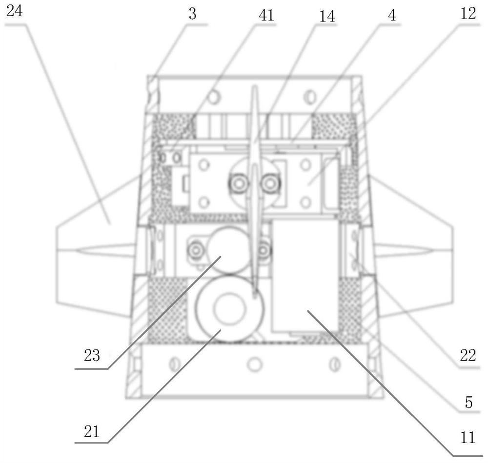
[0005] The purpose of the present invention is to provide an electric steering gear system to solve the problem that the electric steering gear in the prior art cannot satisfy the problem of not only ensuring a smaller volume but also separating and overloading more than 10,000 g when the aircraft is used in a special environment.

Method used


Image

  • An electric steering gear system
  • An electric steering gear system
  • An electric steering gear system

Examples


Embodiment Construction

[0039] In order to make the purpose, advantages and features of the present invention clearer, the electric steering gear system proposed by the present invention will be further described in detail below in conjunction with the accompanying drawings and specific embodiments. Advantages and features of the present invention will be apparent from the following description and claims. It should be noted that all the drawings are in very simplified form and use inaccurate scales, which are only used to facilitate and clearly assist the purpose of illustrating the embodiments of the present invention. In addition, the structures shown in the drawings are often a part of the actual structures. In particular, each drawing needs to display different emphases, and sometimes uses different scales.

[0040] see Figure 1-Figure 4 , the present embodiment provides an electric steering gear system, comprising:

[0041] rudder compartment 3;

[0042] The circuit board 4 located on the ...


PUM


Abstract

The invention discloses an electric steering gear system, comprising: a rudder cabin; a circuit board located on the upper side of the rudder cabin; a linkage steering gear assembly, including a linkage motor, a linkage reducer and a first gear located in the rudder cabin. Potentiometer and linkage rudder; differential steering gear assembly, including differential motor, differential reducer, second potentiometer and differential rudder located in the rudder cabin; wherein, the linkage reducer is arranged on the circuit board in parallel Below, the differential reducer is parallel to the linkage reducer, the direction of the output shaft of the differential motor is parallel to the differential reducer and the differential motor is located below the differential reducer, the direction of the output shaft of the linkage motor is perpendicular to the linkage reducer and the differential The speed reducer has a curved surface that fits closely with the linked motor. As a result, the cross-staggered distribution of the linkage steering gear assembly and the differential steering gear assembly makes the volume of the electric steering gear system smaller. On the premise of ensuring the precise and stable operation of the electric steering gear system, the application range of the electric steering gear system is wider. wide, saving costs.

Description

technical field [0001] The invention relates to the technical field of aircraft stabilization and control, in particular to an electric steering gear system. Background technique [0002] The electric steering gear is the direction control actuator of aircraft such as missiles, rockets, and drones. The aircraft realizes its own pitch, yaw, and roll by controlling the electric steering gear, so as to achieve the purpose of flying according to the predetermined trajectory and heading. The steering gear receives the steering command issued by the flight control system or the missile-borne computer, drives the deflection of the rudder surface in real time, and changes the aerodynamic moment acting on the aircraft, so as to achieve the purpose of controlling the heading and attitude of the aircraft. Depending on the purpose of the aircraft, there are different requirements for the performance indicators of the steering gear. Usually, the performance requirements of the steering ...

Claims


Application Information

Patent Timeline
Patent Type & Authority Patents(China)
IPC IPC(8): F42B10/62B64C13/50
CPCF42B10/62B64C13/50B64U10/00
Inventor 刘小玲杨玫孙世杰刘沛尧李璐孙鹏举朱允进李全福蓝燕任志洁马隽
Owner XIAN AEROSPACE PRECISION ELECTROMECHANICAL INST
Learn More