
Image-based track foreign body detection method

A detection method and track technology, applied in the field of track foreign object detection, can solve the problems of large amount of calculation, large influence of illumination, and high amount of calculation, and achieve the effect of satisfying real-time detection, good recognition effect and low calculation amount

Pending Publication Date: 2019-09-13
NINGBO CRRC TIMES TRANSDUCER TECH CO LTD
View PDF2 Cites 4 Cited by
  • Summary
  • Abstract
  • Description
  • Claims
  • Application Information

AI Technical Summary

Problems solved by technology

[0002] Existing image-based orbital foreign body detection methods can be roughly divided into two categories: one is to use traditional image feature extraction methods, such as sobel transform, Hough transform, wavelet transform, etc., such traditional feature extraction methods, such as Hough transform The amount of calculation is large, and it is difficult to accurately extract the track features when the track conditions are more complicated; the difference and other methods are greatly affected by the light; when the image is convolved with sobel and other operators alone, it is difficult to accurately extract the track edge. It is difficult to stably and effectively extract the features of different foreign objects in complex scenes; the second is to use machine learning related algorithms to train based on the calibrated orbital foreign object sample set. Such methods often have a relatively high amount of calculation and require a large number of calibrated samples data for training, and the structure of the machine learning model is often directly related to the quality of the recognition effect

Method used


Image

  • Image-based track foreign body detection method
  • Image-based track foreign body detection method
  • Image-based track foreign body detection method

Examples


Embodiment Construction

[0030] The present invention will be further described below in conjunction with drawings and embodiments.

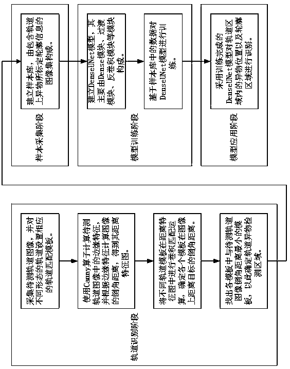
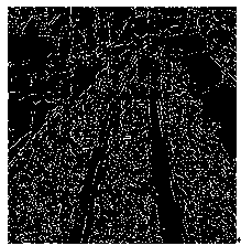
[0031] like figure 1 The schematic block diagram of an image-based track foreign object detection method of the present invention is shown. The track image to be tested is collected. According to the idea that the shape of the train track in the image will not change greatly (the width will not change, the turning angle is limited, and it will always be located on the train track. Central area), set corresponding orbit matching templates for different orbits; use the Canny operator to calculate the edge features in the orbit image to be tested, and calculate the chamfering distance of the image according to the edge features to obtain its distance feature map; The template performs a convolution matching operation in the distance feature map to determine the chamfering distance of each template from the target on the image. The smaller the chamfering distance, the highe...


PUM


Abstract

The invention relates to an image-based track foreign body detection method, which comprises the following steps: acquiring a track image to be detected, and setting corresponding track matching templates for tracks with different forms; calculating an edge feature in the to-be-measured track image by using a Canny operator, and calculating a chamfering distance of the image according to the edgefeature to obtain a distance feature map of the image; carrying out convolution matching operation on different track templates in the distance feature map so as to determine the chamfering distance between each template and the target on the image, the smaller the chamfering distance is, the higher the matching value of the template at the position is; finding out a template with the smallest chamfering distance from the to-be-detected track image in the templates so as to determine a track foreign matter detection area; establishing a sample library, wherein the sample library is composed ofan image set containing contour information calibrated by foreign matters on a track; establishing a DenseUNet model, wherein the DenseUNet model mainly comprises a Dense module, a transition moduleand a deconvolution module; and training the DenseUNet model based on the data in the sample library, and identifying a foreign body position and a contour area in the track area by adopting the trained DenseUNet model.

Description

technical field [0001] The invention relates to a method for detecting foreign matter on a track. Background technique [0002] Existing image-based orbital foreign body detection methods can be roughly divided into two categories: one is to use traditional image feature extraction methods, such as sobel transform, Hough transform, wavelet transform, etc., such traditional feature extraction methods, such as Hough transform The amount of calculation is large, and it is difficult to accurately extract the track features when the track conditions are more complicated; the difference and other methods are greatly affected by the light; when the image is convolved with sobel and other operators alone, it is difficult to accurately extract the track edge. It is difficult to stably and effectively extract the features of different foreign objects in complex scenes; the second is to use machine learning related algorithms to train based on the calibrated orbital foreign object samp...

Claims


Application Information

Patent Timeline
IPC IPC(8): G06T7/00G06T7/13G01N21/88
CPCG06T7/0002G06T7/13G01N21/8851G01N2021/8887G06T2207/10004G06T2207/20081G06T2207/20084
Inventor 石弦韦王鹤鸣郑良广杨玉钊周峰
Owner NINGBO CRRC TIMES TRANSDUCER TECH CO LTD
Learn More