
Sound propagation demonstration teaching aid
A technology of sound transmission and teaching aids, which is applied in the field of teaching display devices to achieve the effect of being easy to use
- Summary
- Abstract
- Description
- Claims
- Application Information
AI Technical Summary
Problems solved by technology
Method used
Image

Examples
Embodiment 1
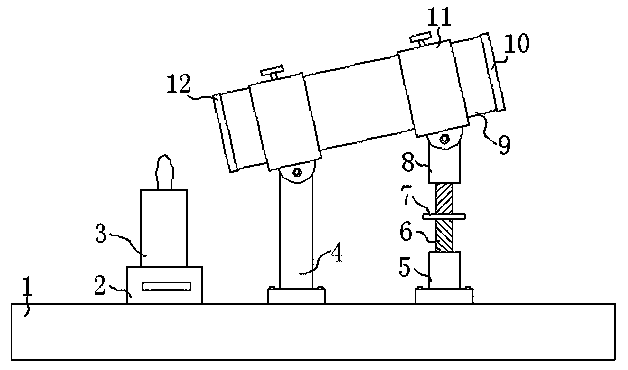
[0024] Embodiment one, with reference to figure 1 , a sound propagation demonstration teaching aid, comprising a base 1, the top of the base 1 is fixed with a pillar 4 and a first threaded pipe 5 by bolts, the top center of the first threaded pipe 5 is embedded with a two-way threaded rod 6, and the two-way threaded rod 6 The other end of the sleeve is provided with a second threaded pipe 8, and the outer wall of the two-way threaded rod 6 is welded with a hand wheel 7, and the tops of the pillar 4 and the second threaded pipe 8 are rotated to be provided with a ring sleeve 11, which slides inside the ring sleeve 11. A straight cylinder 9 is embedded, and the two ends of the straight cylinder 9 are respectively sleeved with a first rubber ring 10 and a second rubber ring 12. The top of the base 1 is located below the second rubber ring 12 and is welded with a fixed ring block 2, and the fixed ring block 2. A candle 3 is inserted in it. When in use, light the candle 3 and turn ...
Embodiment 2
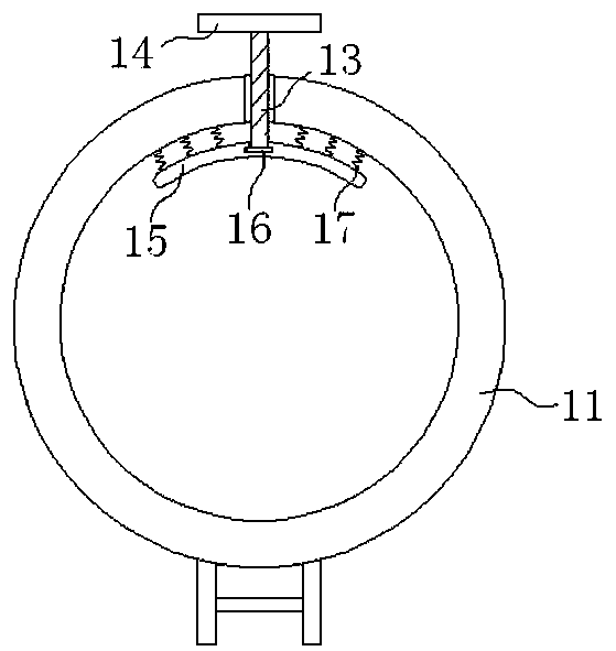
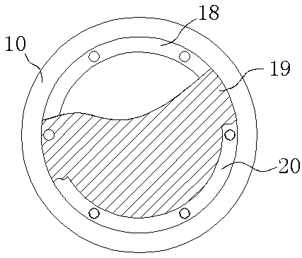
[0025] Embodiment two, refer to figure 2 , image 3 with Figure 4 , the first rubber ring 10 and the second rubber ring 12 are welded with a limit ring 18, the side of the limit ring 18 away from the straight cylinder 9 is fitted with a rubber sheet 19, and the other side of the rubber sheet 19 is provided with a pressure ring 20, and the pressure ring 20 is fixed with the stop ring 18 by bolts, and there are two rubber sheets 19, wherein a circular hole 21 is opened at the center of a rubber sheet 19 located in the second rubber ring 12, and the ring sleeve 11 A screw rod 13 is embedded in the center of the top, and one end of the screw rod 13 located inside the ring sleeve 11 is covered with an arc-shaped plate 15, and one end of the screw rod 13 located in the arc-shaped plate 15 is welded with a rotating block 16, and the screw rod 13 is far away from the arc-shaped plate 15 One end of the handle bar 14 is welded, so that the screw rod 13 is rotated by the hand bar 14,...
Embodiment 3
[0026] Embodiment three, refer to figure 1 with Figure 5 , the fixed ring block 2 is slidingly embedded with a pin rod 22, and one end of the pin rod 22 located on the outside of the fixed ring block 2 is welded with a pull rod 23, and the side of the pull rod 23 near the fixed ring block 2 is welded with two telescopic rods 24, two The other end of two telescopic rods 24 is welded with fixed ring block 2, and the outer side of two telescopic rods 24 is sheathed with two second springs 25, and the two ends of two second springs 25 are connected with fixed ring block 2 and pull bar respectively. 23 welding, the user can pull the pull rod 23, the pull rod 23 will drive the pin rod 22 to move, and the two telescopic rods 24 will also become, so that the second spring 25 is in a stretched state, and the candle 3 can be put into the fixed ring block 2 , loosen the pull rod 23, under the action of the restoring force of the second spring 25, the pin rod 22 will be reset, and the c...
PUM
 Abstract
Description
Claims
Application Information