Battery structure convenient for long-term use

A battery and cell technology, applied in the field of battery structure, can solve the problems of inconvenient use, low heat dissipation efficiency of battery modules, increased use volume, etc., and achieve the effects of convenient use, simple structure, and improved use efficiency

Active Publication Date: 2019-09-13
成都储能云谷信息技术有限公司
View PDF8 Cites 0 Cited by
  • Summary
  • Abstract
  • Description
  • Claims
  • Application Information

AI Technical Summary

Problems solved by technology

[0005] The technical problem to be solved by the present invention is that the heat dissipation efficiency of the existing battery modules is low, and the use volume increases, which is inconvenient to use. The purpose is to provide a battery structure that is convenient for long-term use and solve the problem of using the battery modules

Method used


Image

  • Battery structure convenient for long-term use
  • Battery structure convenient for long-term use
  • Battery structure convenient for long-term use

Examples


Embodiment 1

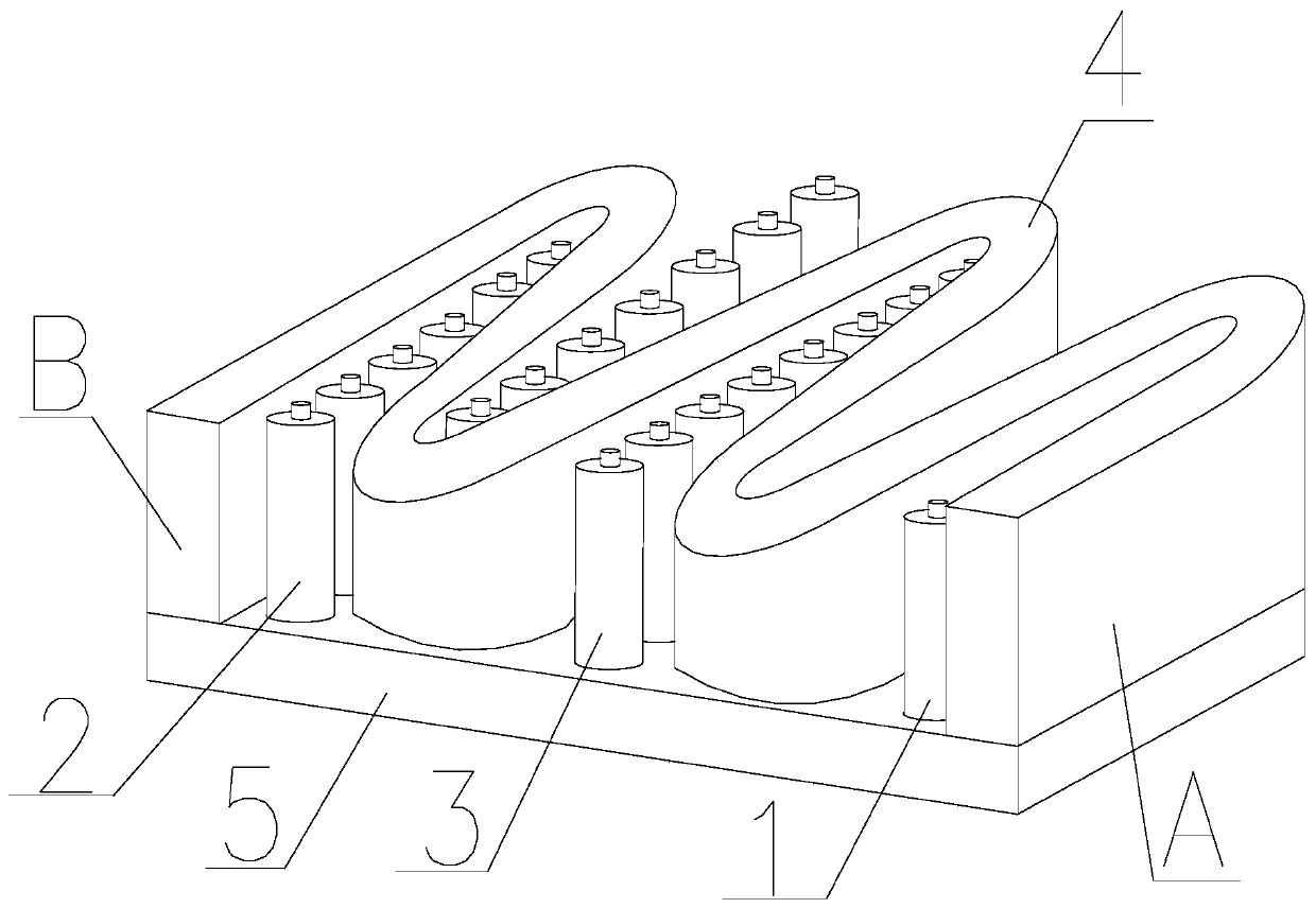
[0030] like Figure 1~3 As shown, the battery structure of the present invention is convenient for long-term use, including a first battery cell 1, a second battery cell 2, and several third battery cells 3 arranged between the first battery cell 1 and the second battery cell 2. The battery cell 1, the second battery cell 2 and the third battery cell 3 include several battery cells arranged side by side, the first battery cell 1, the second battery cell 2 and the third battery cell 3 are arranged side by side, and also include S-type liquid cooling The tube 4, the first battery cell 1, the second battery cell 2 and a number of third battery cells 3 are sequentially arranged on the inner bending side of the S-shaped liquid-cooled tube 4, and the A end and the B end of the S-shaped liquid-cooled tube 4 are respectively connected to the first The sides of the first cell 1 and the second cell 2 are in contact, the inside of the S-shaped liquid-cooled tube 4 is a cavity, and the lo...

Embodiment 2

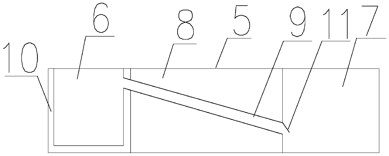
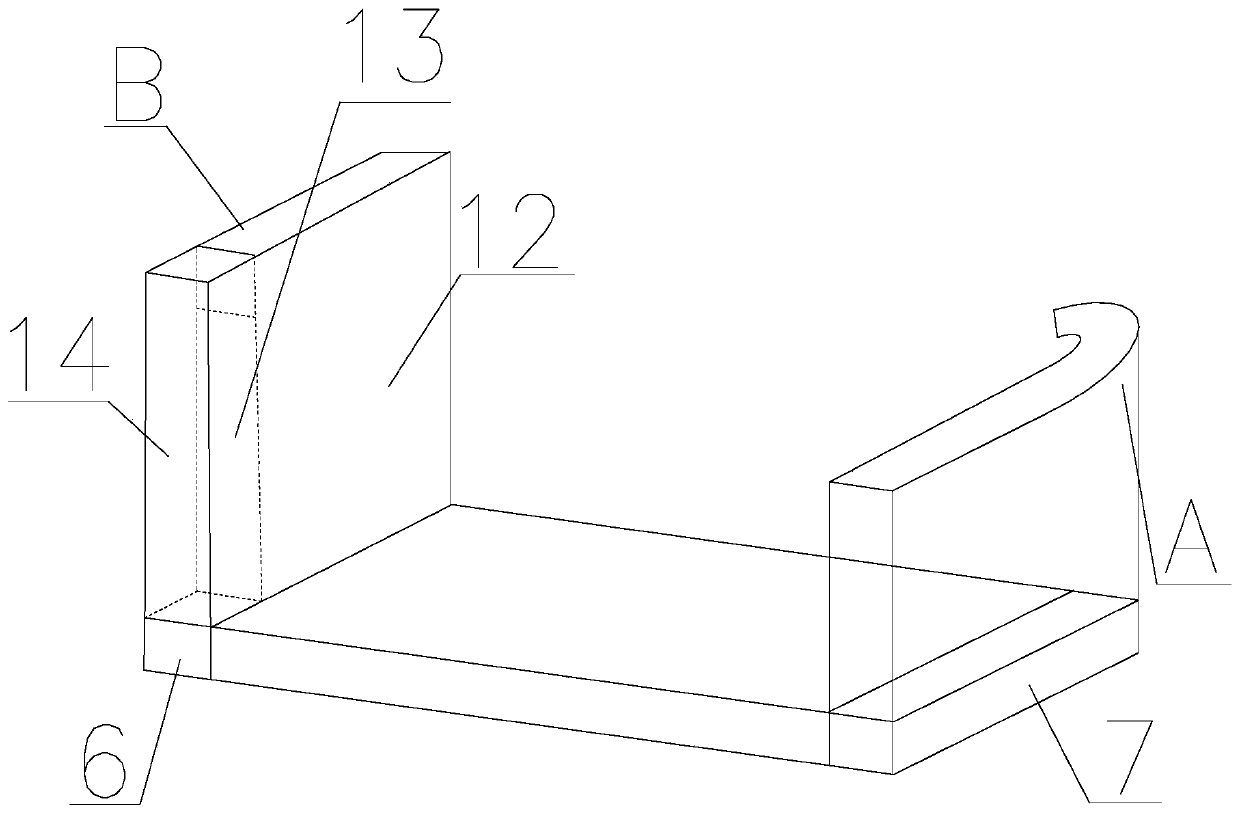
[0034] The battery structure is convenient for long-term use. On the basis of Embodiment 1, the B end of the S-shaped liquid cooling tube 4 is provided with a partition plate 13 perpendicular to the plane where the support platform 5 is located. The partition plate 13 separates the B end into the second One area 14 and the second area 12 two areas, the volume of the first area 14 is 1 / 10 of the volume of the B end, the distance between the upper end of the dividing plate 13 and the upper end of the B end is 2mm, the lower end of the first area 14 and The cooling cavity 6 is connected, and the lower end of the second zone 12 is separated and connected with the cooling cavity 6. The cooling water enters the second zone 12 from the B end, and flows into the first zone 14 from the upper end of the partition plate 13, and then flows into the first zone 14. Cooling cavity 6; the lower end of the A end of the S-shaped liquid cooling tube 4 has the same volume as the upper end of the i...

Embodiment 3

[0037] For a battery structure that is convenient for long-term use, on the basis of Embodiment 2, a conductive end is provided at the end of the supporting platform 5 that is in contact with the battery cell. End A and end B of the S-shaped liquid cooling pipe 4 are fixedly connected to the upper ends of the inlet chamber 7 and the cooling chamber 6 by welding. The S-shaped liquid cooling tube 4 is made of thermally conductive and insulating silicone material.

[0038]When the device is in use, the device is fixed through the sealed shell, and the end of the sealed shell and the battery core away from the support platform 5 is connected through the access device, and the access device and the conductive end make the battery core turn into a connected state. Then use the system through external wires. During the use process, the cooling layer is cooled by a small cooling pump, and the small cooling pump provides power through the battery, and the device can be used for a long ...


PUM


Abstract

The invention discloses a battery structure convenient for long-term use. The A end and the B end of an S-shaped liquid cooling pipe respectively communicate with an inlet cavity and a cooling cavity,cooling water flows into the lower portion of the end A of the S-shaped liquid cooling pipe from the inlet cavity, flows into the cooling cavity from the end B through the inside of the S-shaped liquid cooling pipe, and then flows into the inlet cavity from a connecting pipe after being cooled for circulating cooling. The heat management system of the system has higher efficiency, and compared with the existing heat management system, the system has lower cost, a simpler structure, higher heat dissipation efficiency and more convenient use.

Description

technical field [0001] The invention relates to the battery field, in particular to a battery structure that is convenient for long-term use. Background technique [0002] The structure of the power battery is in a relatively closed environment, and the current is large during operation, and the heat generated is also large, which will directly cause the temperature of the power battery to rise. The reason is that the electrolyte in the lithium battery is charged inside the lithium battery. Conduction, a battery without electrolyte is a battery that cannot be charged and discharged. [0003] The existing power battery module heat dissipation device has low heat dissipation efficiency, uneven heat dissipation, and easy to generate hot spots. In the use of battery modules, the battery is fixed by holding the cylindrical battery on the surface at the positive and negative ends of the battery. It is realized by the splint with round hole. In order to realize the heat dissipati...

Claims


Application Information

Patent Timeline
Patent Type & Authority Applications(China)
IPC IPC(8): H01M10/613H01M10/643H01M10/6556H01M10/6557H01M10/6568H01M10/653H01M10/635H01M2/10
CPCH01M10/613H01M10/635H01M10/643H01M10/653H01M10/6556H01M10/6557H01M10/6568H01M50/20Y02E60/10
Inventor 李平周长城姜萌新
Owner 成都储能云谷信息技术有限公司
Why Eureka
Try Eureka