Supercharge Your Innovation With Domain-Expert AI Agents!

Method and system for controlling commutation failure recovery of direct current system

A commutation failure recovery control technology, applied in the field of power systems, can solve problems such as system frequency collapse, DC power transmission interruption, overheating of the converter valve, etc., and achieve the effect of preventing subsequent commutation failure failures and improving fault recovery capabilities

Active Publication Date: 2019-09-13
ELECTRIC POWER RES INST OF STATE GRID ZHEJIANG ELECTRIC POWER COMAPNY +1
View PDF19 Cites 3 Cited by
  • Summary
  • Abstract
  • Description
  • Claims
  • Application Information

AI Technical Summary

Problems solved by technology

Commutation failure failures will cause problems such as interruption of DC power transmission, overheating of converter valves, transformer bias, and relay protection malfunctions; at the same time, according to the current UHV DC control and protection strategy, when multiple consecutive commutation failures occur cause DC blocking
If multiple circuits of high-power DC are lost at the same time, there is a risk of system frequency collapse in the receiving end system, which may cause large-scale power outages

Method used


Image

  • Method and system for controlling commutation failure recovery of direct current system
  • Method and system for controlling commutation failure recovery of direct current system
  • Method and system for controlling commutation failure recovery of direct current system

Examples


Embodiment 1

[0057] This embodiment provides a recovery control method for DC system commutation failure based on recovery track prediction.

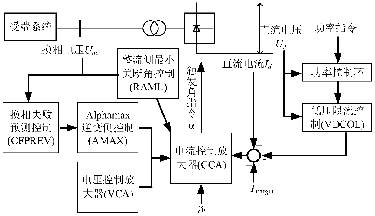
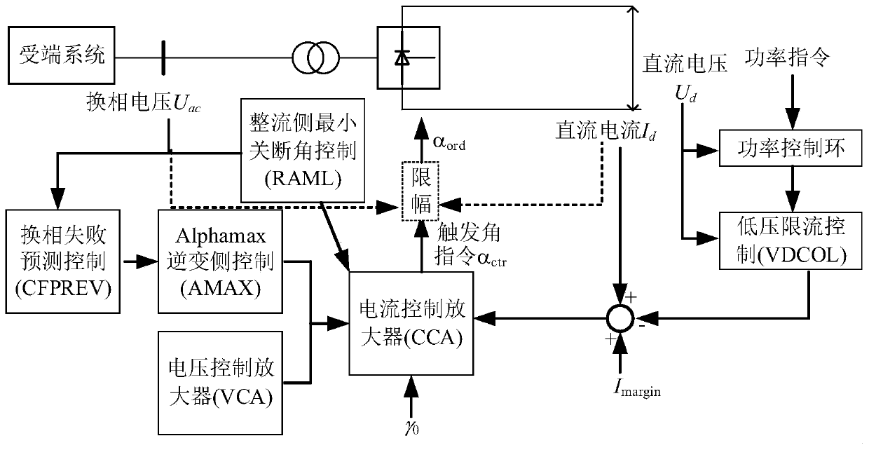
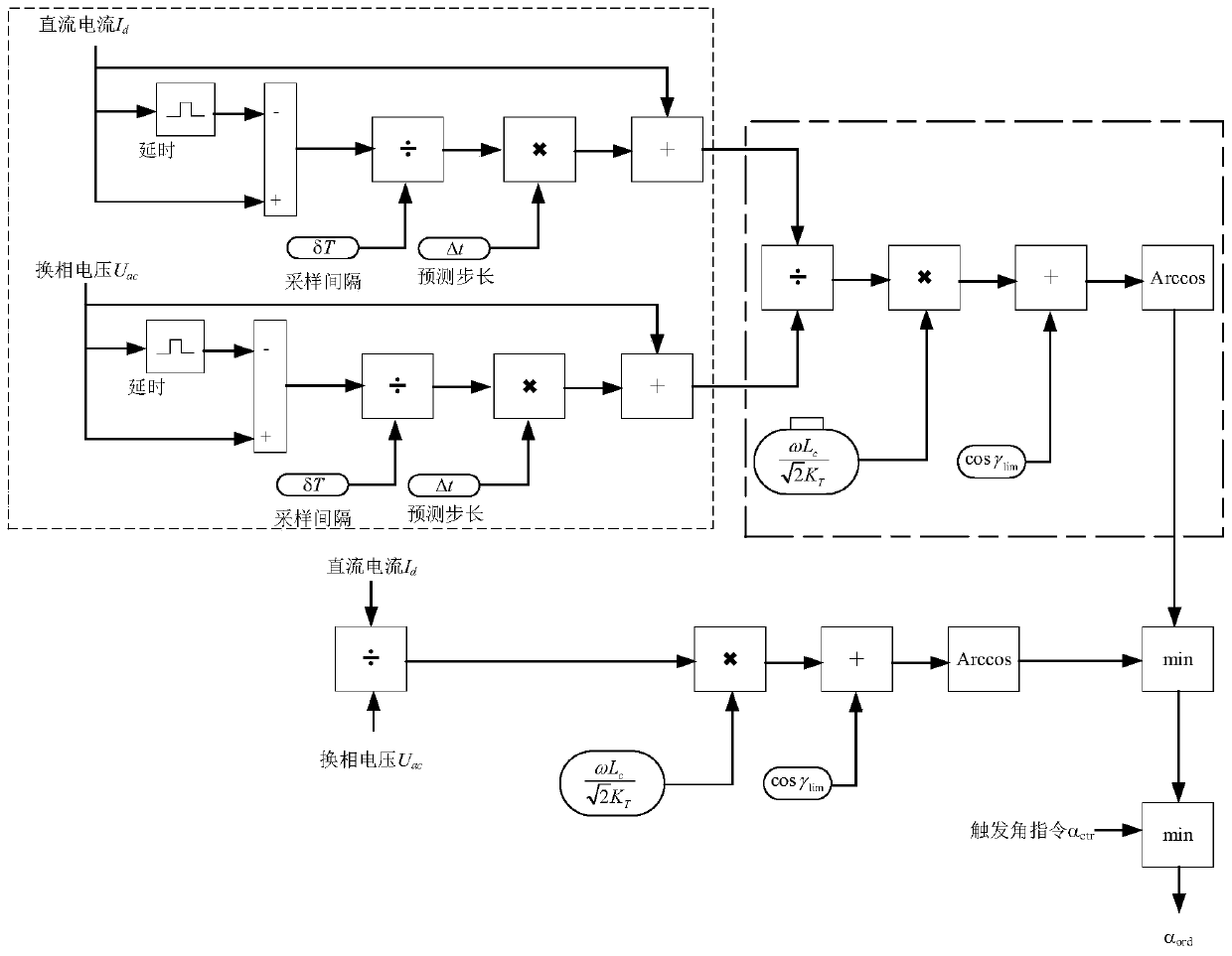
[0058] Such as figure 1 As shown, the converter station of the receiving end system generates the firing angle command of the converter valve through multiple control links such as the power control link and the low-voltage current limiting control link according to the power command, DC voltage, DC current and commutation voltage value. In the present invention, a dynamic limiter link is added to the trigger angle command generated by the current control amplifier, and the limit value is dynamically adjusted according to the commutation voltage and the DC current state, such as figure 2 shown. Specifically, the commutation voltage U on the AC side is first predicted c , DC current I d recovery trajectory, such as image 3 Shown in the dotted box:

[0059] 1. Prediction of recovery trajectory after commutation voltage fault:

[0060] u c (t+...

Embodiment 2

[0078] This embodiment provides a DC system commutation failure recovery control system based on recovery trajectory prediction, which includes a recovery trajectory prediction unit, a delayed firing angle maximum calculation unit, and a delayed firing angle controller instruction upper limit unit.

[0079] The recovery trajectory prediction unit: based on the commutation voltage on the AC side and the DC current on the DC side, predict the recovery trajectory of the commutation voltage and the DC current by using a linear prediction method;

[0080] The maximum delayed firing angle calculation unit: taking the minimum value of the arc-extinguishing angle as the safe operation boundary, respectively calculating the maximum delayed firing angle of the current operating state and the prediction of the system recovery trajectory after a fault;

[0081] The delayed firing angle controller command upper limit unit: take the minimum value of the two delayed firing angle maximum value...


PUM


Abstract

The invention discloses a method and system for controlling commutation failure recovery of a direct current system. Multiple direct current blocking accidents have already occurred since a direct current power transmission system puts into operation, and recovery control for commutation failure faults of the direct current system is extremely important for improving the safety stability of the system. According to the method for controlling commutation failure recovery of the direct current system, recovery tracks of commutation voltage and direct current are estimated by using a liner prediction method based on commutation voltage on alternating current side and direct current on direct current side; then, the minimum angle of an extinction angle is taken as a boundary of safe operation,the maximum values of delay trigger angles predicted by system recovery tracks in current state and after the faults are calculated respectively; and finally, the minimum value in the two values is taken as the maximum value in the final output amplitude limiting link of a delay trigger controller. The variation trend of system state is considered, dynamic amplitude limiting is adopted for a delay trigger angle command, the recovery of the direct current system can be prevented from being too quick to cause the occurrence of subsequent commutation failure in the recovery process of the faults.

Description

technical field [0001] The invention belongs to the technical field of electric power systems, and relates to the recovery control of converter station faults in traditional high-voltage direct current transmission projects, in particular to a DC system commutation failure recovery control method and control system based on recovery trajectory prediction. Background technique [0002] In actual operation, there have been many failures of single-circuit DC continuous commutation or multi-circuit simultaneous commutation failures in AC-DC hybrid systems due to AC system failures. Commutation failure failures will cause problems such as interruption of DC power transmission, overheating of converter valves, transformer bias, and relay protection malfunctions; at the same time, according to the current UHV DC control and protection strategy, when multiple consecutive commutation failures occur resulting in DC blocking. If multiple high-power DCs are lost at the same time, there...

Claims


Application Information

Patent Timeline
IPC IPC(8): H02J3/36
CPCH02J3/36H02J3/001Y02E60/60
Inventor 沈轶君吴跨宇周永智楼伯良陆承宇熊鸿韬卢嘉华华文房乐张建承
Owner ELECTRIC POWER RES INST OF STATE GRID ZHEJIANG ELECTRIC POWER COMAPNY
Features
  • R&D
  • Intellectual Property
  • Life Sciences
  • Materials
  • Tech Scout
  • Unparalleled Data Quality
  • Higher Quality Content
  • 60% Fewer Hallucinations
Learn More